Microcontroller projects
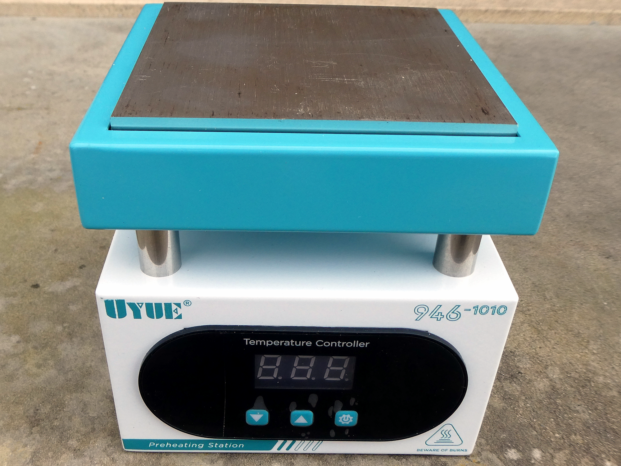
UYUE 946-1010: Convert a preheating station in a reflow solder station
last updated: 2024-07-08
* This project and it's documentation is due to time problems on hold. I had no time to write the complete software. It will be finished in the next months :). *
Quick links
Introduction
In a video I saw, bitluni solder SMD components on a preheating station. I've tested a reflow oven (https://www.weigu.lu/other_projects/baking_smd/index.html), but for small pieces or to unsolder things I thought such a preheating station would be cool (or hot). When buying the station I did not pay attention and bought a 110 V station instead of a 220 V station. So I ordered a second station and will hack the first (or both) to get a reflow solder station :).
Hacking
As Denis Bodor (Hackable Magazine) wrote, there is no better thing to do during a WE than hacking or reverse engineering a device :).
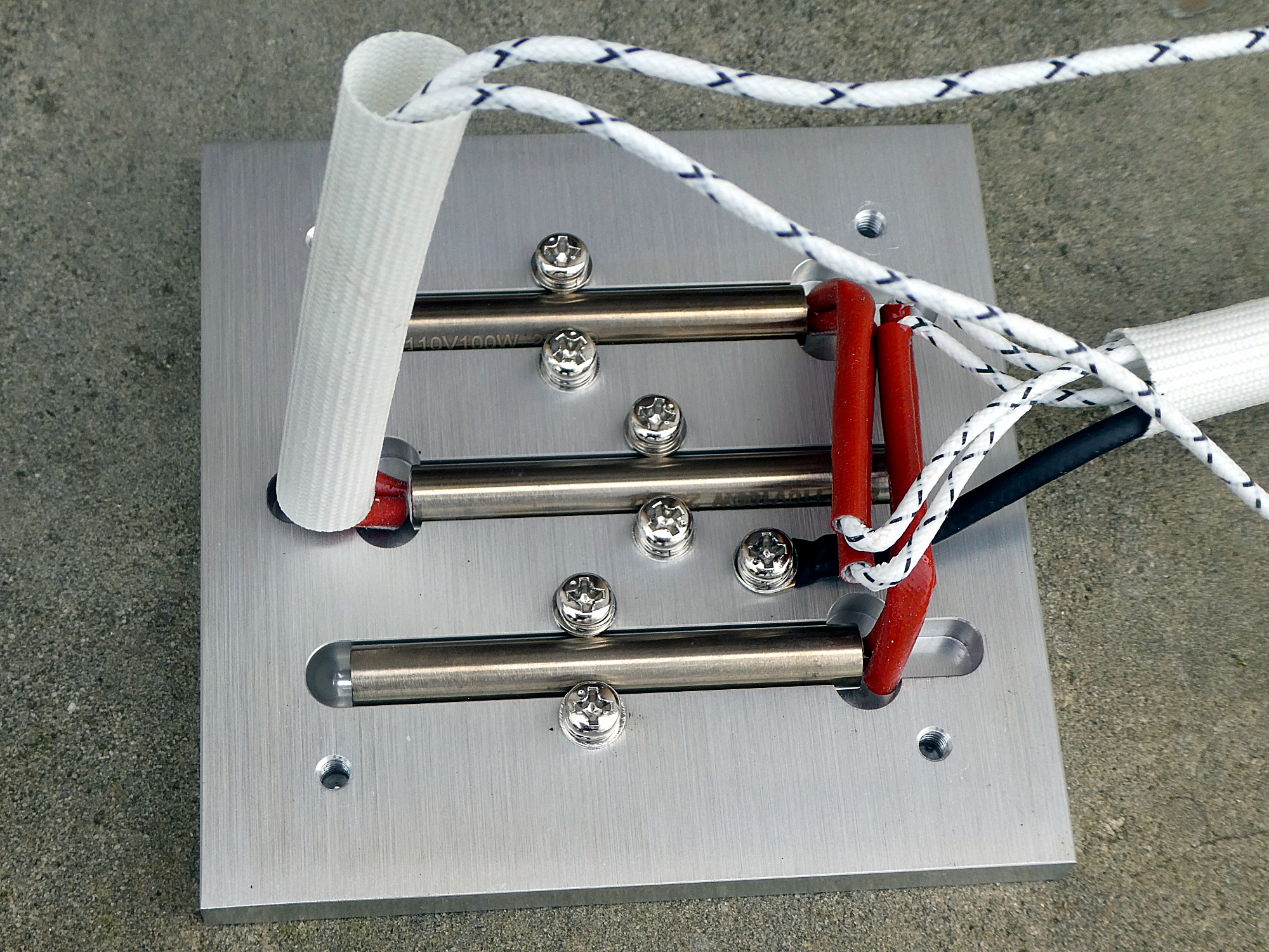
So I have 2 UYUE 946-1010 preheating station. Both station are labeled with 400W. By opening the stations I found:
110 V Station:
3 heating elements (8 mmx60 mm) 110 V/100 W
R = 110 V²/100 W = 121 Ω, Rtotal = 40 Ω
Measured R = 40.3 Ω
Hotplate 10x10x 8.3mm³
220 V Station:
2 heating elements (8 mmx60 mm) 220 V/150 W
R = 220 V²/150 W = 323 Ω, Rtotal = 161 Ω
Measured R = 155 Ω
Hotplate 10x10x 6.1mm³
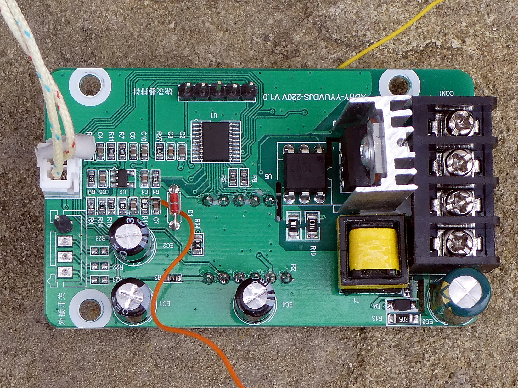
Both station have the same PCB! labeled YYUVDJS-220V V1.0.
I could use the 110 V station with 220 V and a max 25% PWM, but this is a little risky, so I ordered 3 heating elements 220 V/100 W
By looking at the components I found a BTA16-800B Triac with an EL3083 zero cross TRIAC driver to switch the heating elements. A chip labeled SZ2525C (7-Pin) is an AC/DC converter like an LNK304GN. Thanks to Basil Hussain here is the datasheet: [Datasheet SZ2525C AC/DC converter (chinese)](https://www.lcsc.com/datasheet/lcscdatasheet2405210914HaloChip-SZ2525CTGTC22434960.pdf. The DC output voltage is followed by an classical 78L05 to produce 5 V.
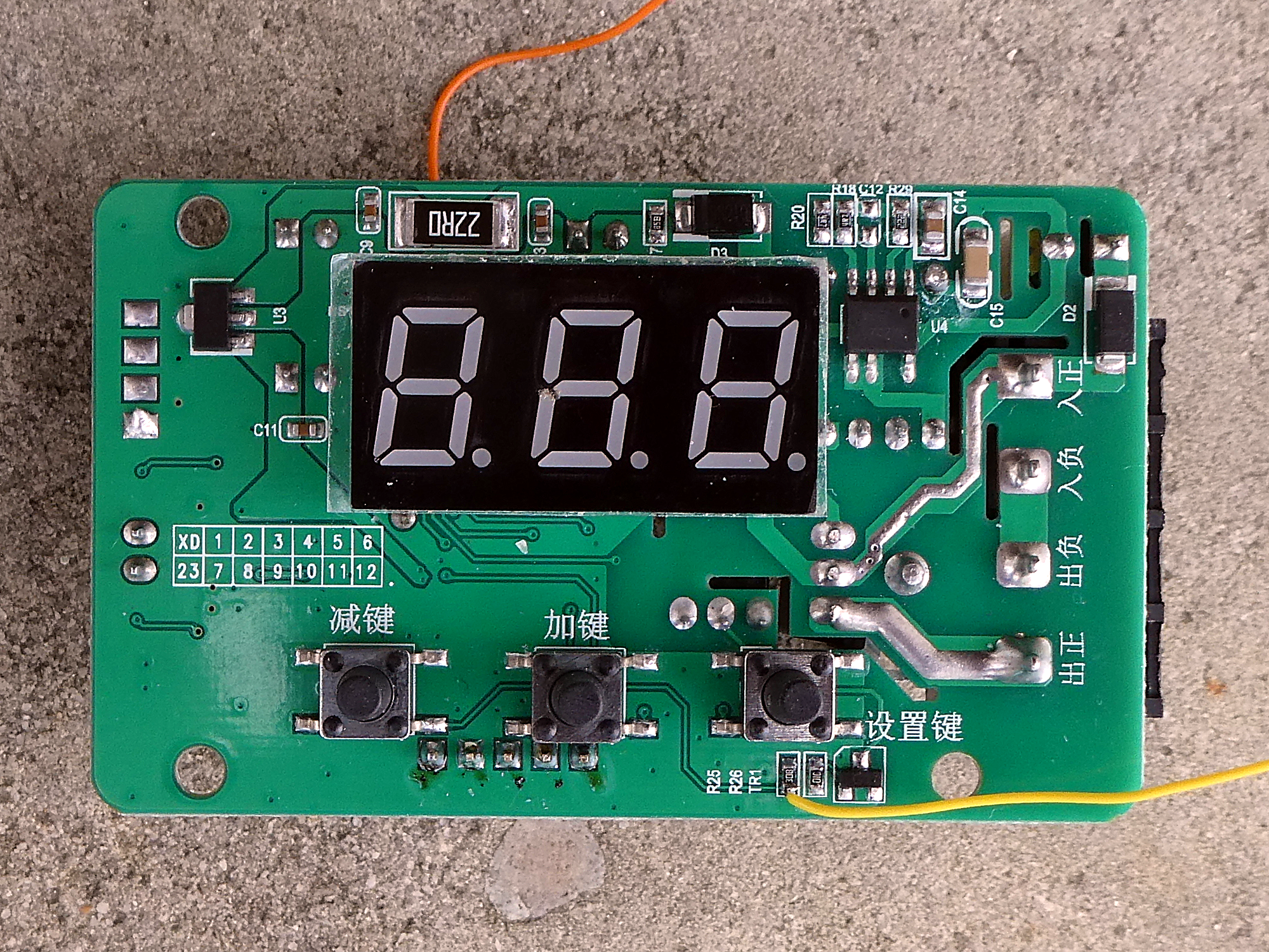
A 5 pin header (not soldered) is connected to the 20 pin microcontroller. The µC is not labeled and I thought after a little research we have an STM8103F3. Basil wrote me that this was not likely, as ST parts always have markings and this chip doesn't. He also wrote the chip is highly likely one of many Asian-brand STM8S003-pin-compatible MCUs that are typically based on 8051 or ARM Cortex M0+ processors.
As this gets complicated to program and newer chips also can get completely locked, so reprogramming is not possible, I will replace the chip with an ESP32.
The temperature sensor is an K thermocouple type (specs of the station) and the small voltage is amplified with an LM321 opamp.
The 3 digit 7 segment display has his series resistors in the common anode circuit wich is not professional because we get different luminosity for different digits.
And here is the reverse engineered circuit :)

Then I measured the voltage on pin PA1 (5) by changing the temperature
| Temperature [°C] | Voltage [mV] | Temperature [°C] | Voltage [mV] | Temperature [°C] | Voltage [mV] |
|---|---|---|---|---|---|
| 110 | 663 | 210 | 990 | ||
| 20 | 378 | 120 | 698 | 220 | 1013 |
| 30 | 401 | 130 | 732 | 230 | 1045 |
| 40 | 431 | 140 | 763 | 240 | 1080 |
| 50 | 464 | 150 | 797 | 250 | 1111 |
| 60 | 498 | 160 | 831 | 260 | 1143 |
| 70 | 531 | 170 | 856 | 270 | 1176 |
| 80 | 565 | 180 | 889 | 280 | 1207 |
| 90 | 600 | 190 | 928 | 290 | 1243 |
| 100 | 630 | 200 | 958 | 300 | 1274 |
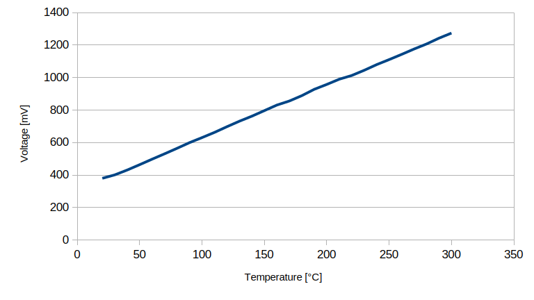
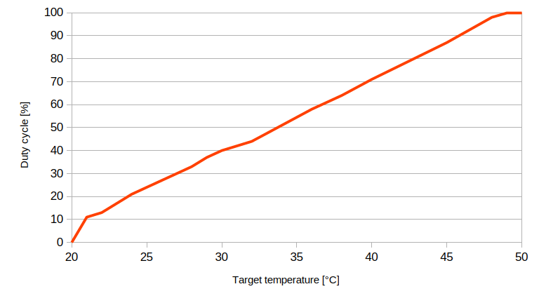
Ok we got a linearity with about 3.2 mV/°C. After this I measered the PWM on pin PA3 (10) without heating. The ambient temperature is about 20°C:
| Target temp. [°C] | Duty cycle [%] | Target temp. [°C] | Duty cycle [%] | Target temp. [°C] | Duty cycle [%] |
|---|---|---|---|---|---|
| 20 | 0 | 30 | 40 | 40 | 71 |
| 21 | 11 | ||||
| 22 | 11 | 32 | 44 | ||
| 23 | 17 | ||||
| 24 | 21 | 34 | 51 | ||
| 25 | 24 | 45 | 87 | ||
| 26 | 27 | 36 | 58 | ||
| 27 | 30 | ||||
| 28 | 33 | 38 | 64 | 48 | 98 |
| 29 | 37 | 49 | 100 |
This can give us a hint for the PID regulation. Duty cycle increases about 3%/°C.
Hardware
First I removed the microcontroller (hot air) and the 7 segment display.
I will replace the 7 segment display with an LCD screen. I found an LCD IPS TFT screen that fits nicely in the existing cut out. It is an 0.96" display with 80x160 pixel and an ST77355 driver. You find it on amazon and aliexpress (0.96" 80X160 (RGB) IPS 65k ST7735). We can use the ST7735 library from adafruit in the Arduino IDE.

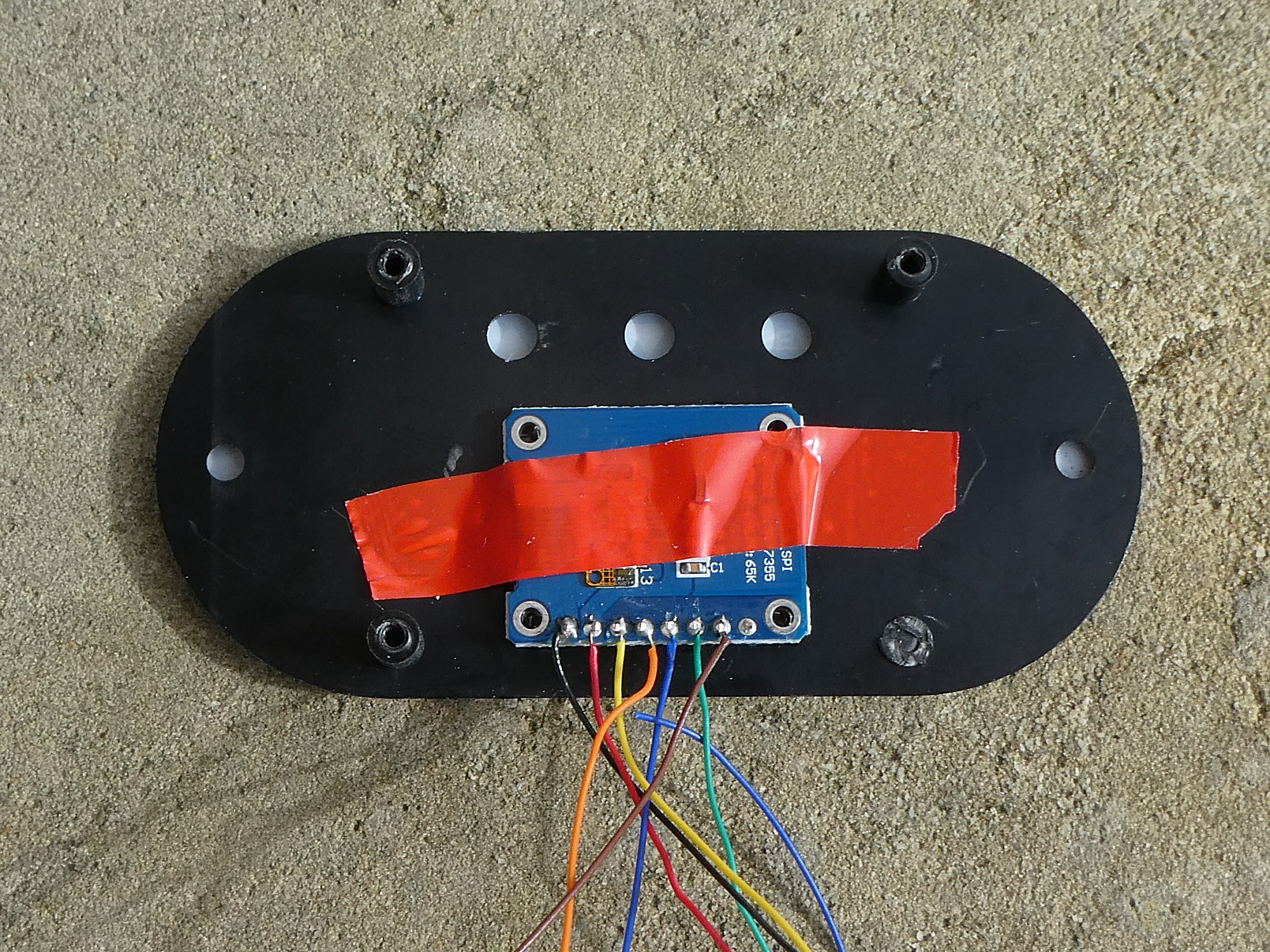
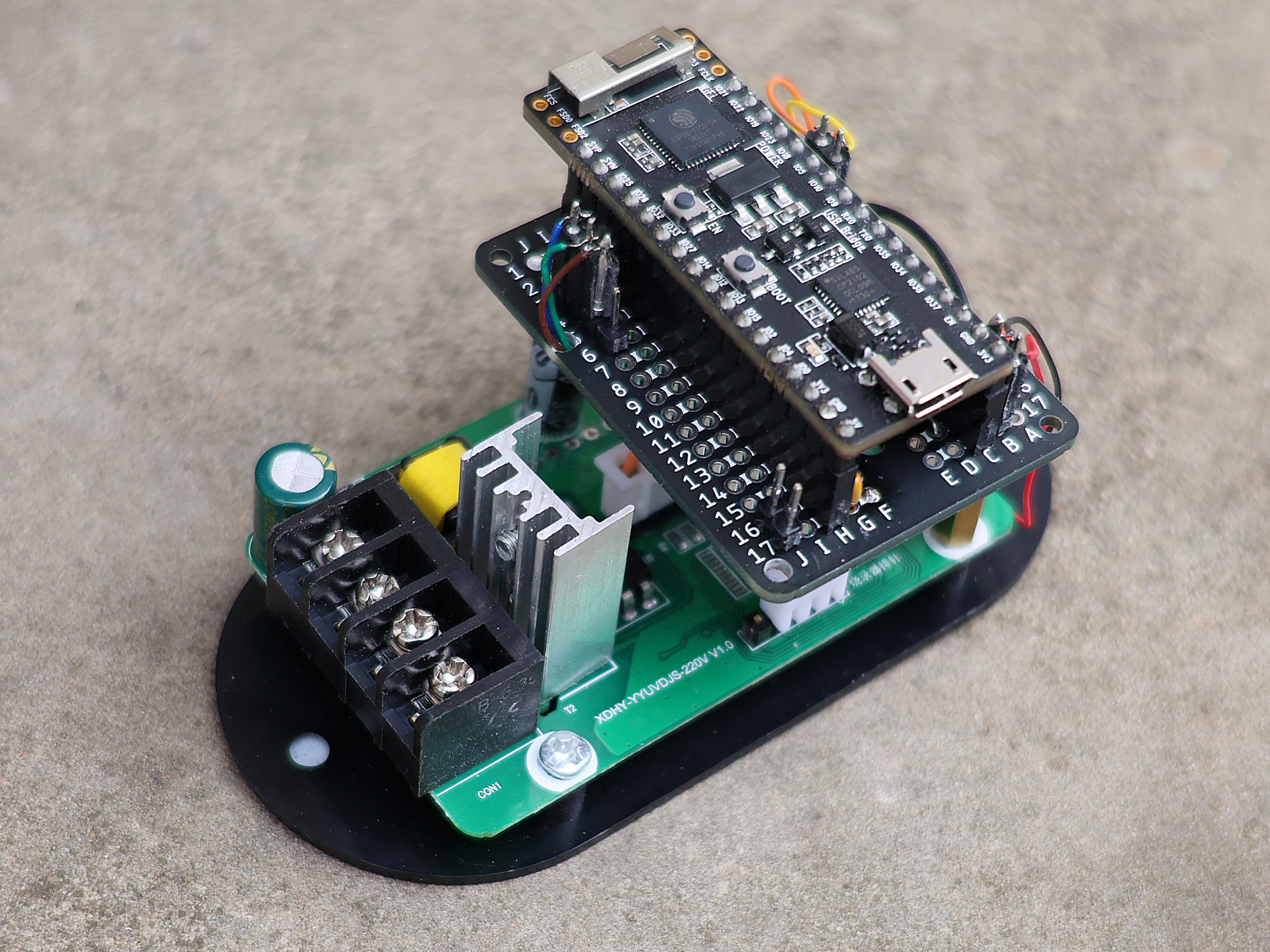
The display works over SPI (the markings of the pins are confusing as SCL and SDA are mostly used with I2C). I needed an ESP32 and found an older board in my tinker box. It is an ESP32-Pico_kit_V4 from Espressif. I soldered it to a prototyping board that is fixed to the original PCB.
Here are the connections with the display:
| TFT pin | ESP32 pin |
|---|---|
| GND | GND |
| VCC | 3V3 |
| SCL | GPIO18 VSPICLK (CLK) |
| SDA | GPIO23 VSPID (MOSI) |
| RES (RESET) | GPIO25 |
| DC (Data/Command) | GPIO26 |
| CS (Chip select) | GPIO32 |

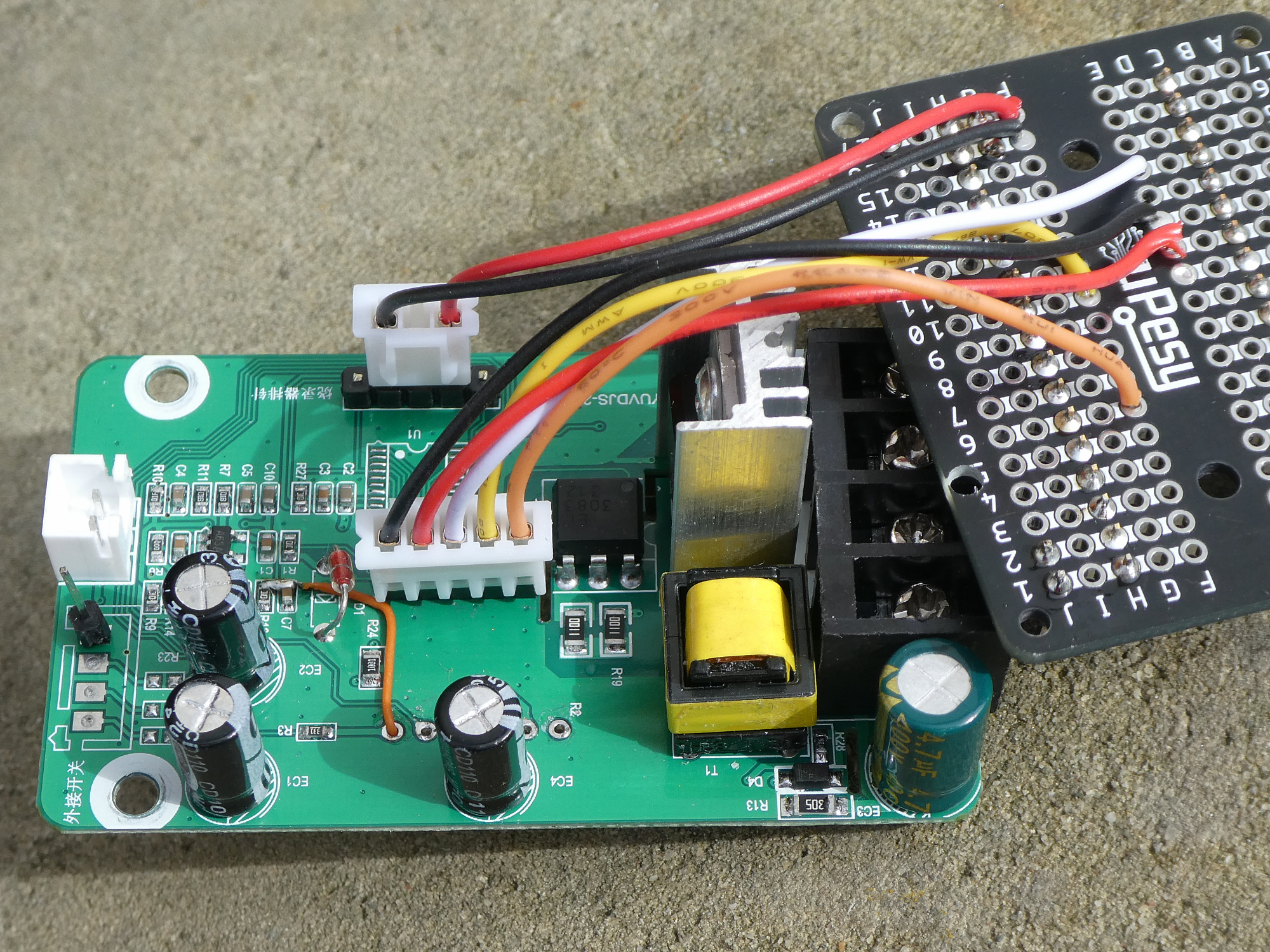
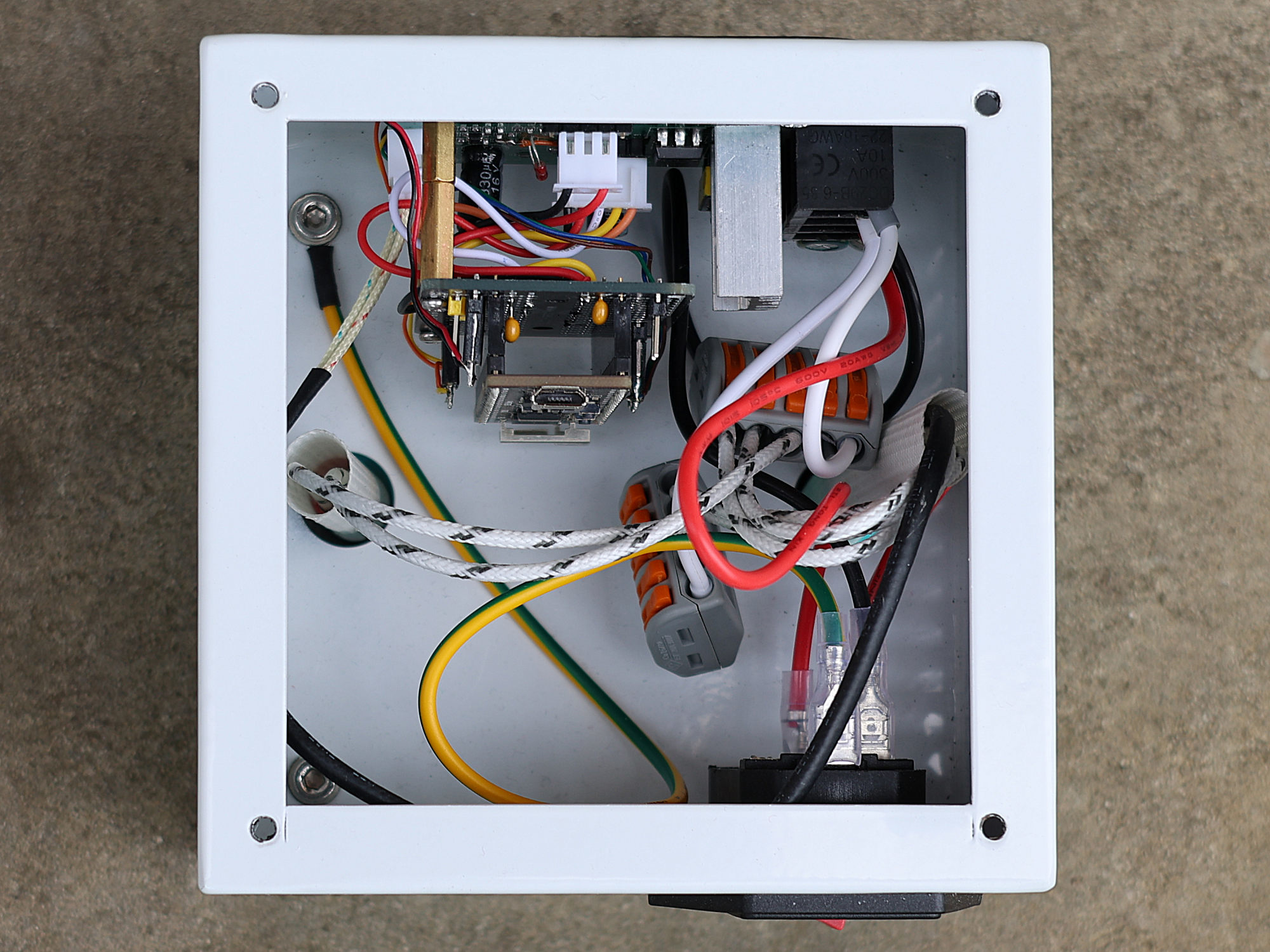
I had problems with GPIO34, GPIO35 and GPIO19 (used by SPI) as Input pins, so the connections to the prototyping board on the photo are no more correct.
I used a 5 pol header that I soldered into the holes of the 7 segment pins to connect the buttons, the Triac control to heat up and the temp sensor:
| original PCB pin | ESP32 pin |
|---|---|
| Button SET | GPIO21 |
| Button UP | GPIO22 |
| Button DOWN | GPIO9 |
| Triac control | GPIO13 (PWM) |
| Temp sensor | GPIO37 (ADC) |
Here is the circuit. New connections in red.

Software
Downloads
Everything will be on github
