Microcontroller projects
Using PIO state machines on the Raspberry Pi Pico
last updated: 2025-09-02
Work in progress
Intro
This is all the fault of Jean-Claude Feltes.
I really like Python, but struggled with Micropython, especially because it is slow. But the Pico has PIO state machine that are fast. The Pico is manufactured in Europe an has now even a RISC-V processor, so definitely I have to use it in parallel to the ESPs and the Teensys. And there is always the possibility to use C or C++ with the Pico SDK.
It is not very intuitive to program the PIO state machines. But Jean-Claude has already done a big part of the work and documented it (in German). Also the videos from David are really good and helpful: https://www.youtube.com/@LifewithDavid1/videos
I will try to focus here on some practical examples.
Some images used on this page are sourced from the Raspberry Pi Pico datasheet, which is licensed under the Creative Commons Attribution-ShareAlike 4.0 International (CC BY-SA 4.0) license. © 2012-2024 Raspberry Pi Ltd. You can view the full datasheet and license details here: https://datasheets.raspberrypi.com/pico/pico-datasheet.pdf.
PIO blocks, state machines and instructions
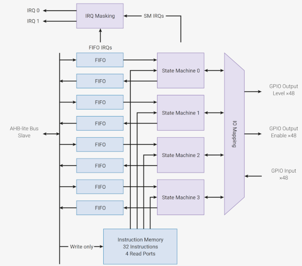
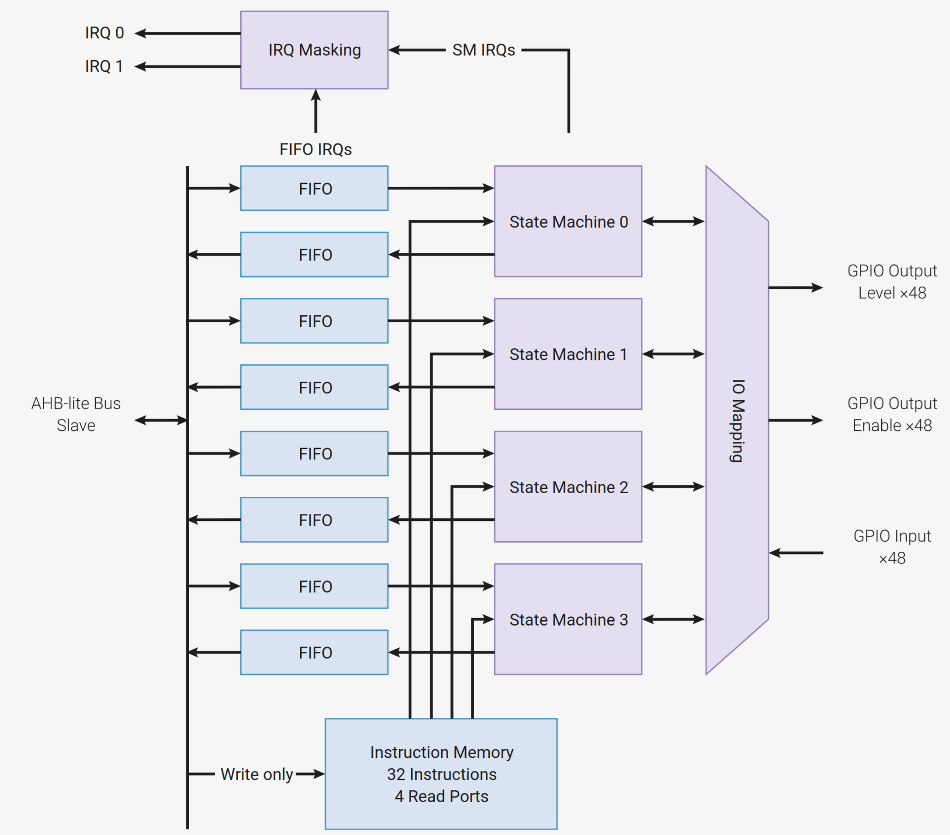
The original Pi PICO (RP2040) contains 2 identical PIO blocks with 4 state machines per block. The 4 state machines (SM) share the same memory! The newer Pico 2 (RP2350) has 3 PIO blocks (12 SM).

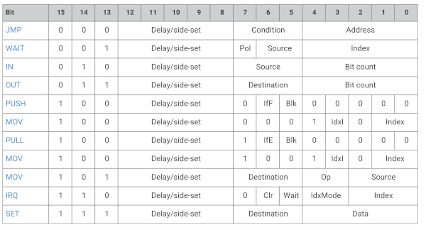
You find all the relevant commands to use with micropython here: https://docs.micropython.org/en/latest/library/rp2.html. Here is an little overview from the datasheet:

Jean-Claude created the following block diagram, helping to understand the different flows:
Toggle one pin
There are only 9 commands, but they are powerful! and there is often more than one way to do things. Let's start with a simple clock signal (square wave 50%) with 1MHz.
Set
    """ This code toggles a pin at 2MHz using a state machine
        to get a clock signal of 1MHz with the set command. """

    from time import sleep
    from machine import Pin, freq
    from rp2 import PIO, StateMachine, asm_pio
    freq(200_000_000) # set the Pico clock

    FREQ = 1_000_000
    CLOCK_PIN = Pin(15)

    # State machine outputs clock with 1MHz (2 clock cycles)
    @asm_pio(set_init = PIO.OUT_LOW)
    def toggle_clock():
        set(pins, 1) # sets the pin defined with set_base
        set(pins, 0) # sets the pin low

    # Initialize the state machine
    sm0 = StateMachine(0, toggle_clock, freq = 2*FREQ, set_base = CLOCK_PIN)

    sm0.active(1) # Activate the state machine to generate the clock signal
    sleep(10)     # Run the clock signal for 5 seconds
    sm0.active(0) # Deactivate the state machine
After the @asm_pio statement we define an assembler function that runs in a loop.
Important are the set_init and the set_base command to define the state and the pin.
We use state machine number 0. After some time (sleep()) we stop the state machine.
Every command needs one clock cycle. The PIO frequency needs to be the double of the
signal frequency.
As the Pico's are now officially supported up to 200MHz we can test our program with the maximal frequency of 200MHz!
Sideset
It is possible to set pins side to a command. This is very helpful e.g. to create a clock
signal simultaneously with a parallel output. Here we will use the no operation command
(nop()does nothing but uses one clock cycle) with a sideset pin to create our clock.
Important are the sideset_init and the sideset_base command to define the pin.
    """ This code toggles a pin at 2MHz using a state machine
        to get a clock signal of 1MHz with the sideset command. """

    from time import sleep
    from machine import Pin, freq
    from rp2 import PIO, StateMachine, asm_pio
    freq(200_000_000) # set the Pico clock

    FREQ = 1_000_000
    CLOCK_PIN = Pin(15)

    # State machine outputs clock with 1MHz (2 clock cycles)
    @asm_pio(sideset_init = PIO.OUT_LOW)
    def toggle_clock():
        nop() .side(1)  # sets the pin defined with set_side
        nop() .side(0)  # sets the pin low

    # Initialize the state machine
    sm0 = StateMachine(0, toggle_clock, freq = 2*FREQ, sideset_base = CLOCK_PIN)

    sm0.active(1) # Activate the state machine to generate the clock signal
    sleep(10)     # Run the clock signal for 5 seconds
    sm0.active(0) # Deactivate the state machine
Out
The out() command is mostly used to out what is in the OSR register.
The OSR register is often filled with pull() (or autopull) from the TX FIFO register
that can be accessed from the Micropython main loop.
But Micropython is not very fast. I measured the time of a for loop with 1.6s for
100000 passes. So one pass needs 16µs (62.5kHz). This is not fast enough
to fill the register if we use one bit. But with 32 bit we are just fast enough to reach
our goal of 1MHz :). So here is the code:
    """ This code toggles a pin at 1MHz using a state machine using
        the out command with 32 bit and autopull enabled. """

    from time import sleep
    from machine import Pin, freq
    from rp2 import PIO, StateMachine, asm_pio
    freq(200_000_000) # set the Pico clock

    FREQ = 1_000_000
    CLOCK_PIN = Pin(15)

    # State machine outputs clock with 1MHz (6 clock cycles)
    @asm_pio(out_init = PIO.OUT_LOW, out_shiftdir = PIO.SHIFT_RIGHT, autopull = True, pull_thresh = 32)
    def toggle_clock():
        out(pins, 1)       # Output 1 bit from the OSR to the pin (pin goes LOW)

    # Initialize the state machine
    sm0 = StateMachine(0, toggle_clock, freq = 2*FREQ, out_base = CLOCK_PIN)

    sm0.active(1) # Activate the state machine to generate the clock signal
    for i in range(1000000): # Load the TX FIFO register 1000000 times
        sm0.put(0b01010101010101010101010101010101) # Put a value of 0 in the TX FIFO register
    sm0.active(0) # Deactivate the state machine
Important are out_init, out_shiftdir. With autopull = True we avoid the pull()
command an so one clock cycle and pull_thresh = 32 tells to use all 32 bit from the
register. set_base defines the pin.
Loading the TX FIFO register takes one clock cycle. so the frequency must be 2MHz.
So clearly out is not the way to go for a simple square wave, but is better used for parallel output. We could also use a scratch register to set the OSR, but I think this approach is not elegant.
PWM
Now let's try a PWM signal with 10% duty cycle:
""" This code creates a PWM of 1MHz, duty cycle 10%. """

from time import sleep
from machine import Pin, freq
from rp2 import PIO, StateMachine, asm_pio
freq(200_000_000) # set the Pico clock

FREQ = 1_000_000
CLOCK_PIN = Pin(15)

# State machine outputs clock with 1MHz (2 clock cycles)
@asm_pio(set_init = PIO.OUT_LOW)
def toggle_clock():
    set(pins, 1) # sets the pin defined with set_base
    set(pins, 0) [8] # sets the pin low and add 8 clock cycles

# Initialize the state machine
sm0 = StateMachine(0, toggle_clock, freq = 10*FREQ, set_base = CLOCK_PIN)

sm0.active(1) # Activate the state machine to generate the clock signal
sleep(10)     # Run the clock signal for 5 seconds
sm0.active(0) # Deactivate the state machine
This is the same as our first program. With the square brackets we can add up to 31 clock cycles to a command. So our second command get's here 1+8 = 9 clock cycles. In total we have 10 clock cycles, so the PIO frequency needs to be 10 times higher than the PWM frequency.
Parallel output to more pins
 ](png/PIOblocklevel_diagram.png)
-->
Downloads
- Everything on github: https://github.com/weigu1/rpipicopio
Interesting links
- https://datasheets.raspberrypi.com/rp2040/rp2040-datasheet.pdf
- https://datasheets.raspberrypi.com/rp2350/rp2350-datasheet.pdf
- https://www.youtube.com/@LifewithDavid1/videos
- https://docs.micropython.org/en/latest/library/rp2.html https://www.ti.com/lit/ds/symlink/sn74hc165.pdf https://www.ti.com/lit/ds/symlink/sn74hc595.pdf
