Microcontroller projects
Solar_master: Monitor your PV panels
* on hold because my display broke and there is a problem with the dual use of pins for SD CARD ans serial modbus *
last updated: 2025-09-27
Intro
After more then 20 years of use some of my solar panels had to be rewired to fit my new battery system. At the same time, they are cleaned and it would be interesting to get the U/I curve of the panels to compare them and detect faulty or weak panels. I wrote this two years ago and developed and used the solar_master, but had no time to document it. This will be done now :) :
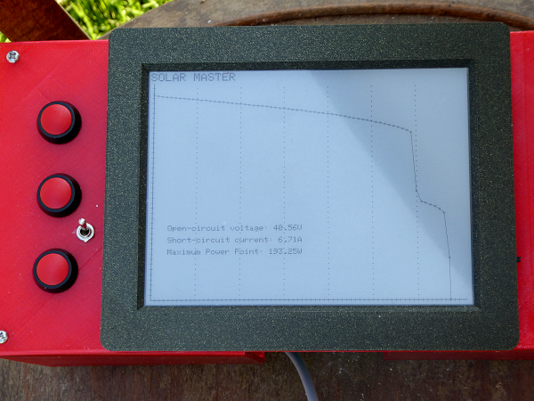
I needed a load to change the current and measure the voltage. And after a short search I found an electronic 500W load on Aliexpress with a resistance up to 1000 Ω. The load is from the firm SOUSIM (type14 0-100 V 0-20 A) and you will still find it on Aliexpress in 2025 for about 75€. The challenge was to understand the communication with the load, ass all documentation was in Chinese (and my Chinese isn't so good ;)).
For the rest I used mainly an old Inkplate 6 (from 2020). The Inkplate 6 has a recycled 6 inch e-paper display (800x600), with an ESP32 and an SD card slot. The other cool things of the inkplates is that they are 100% open-source for both software and hardware. I think there is no problem to use a newer Inkplates : https://soldered.com/product/inkplate-6-6-e-paper-board/.
Features
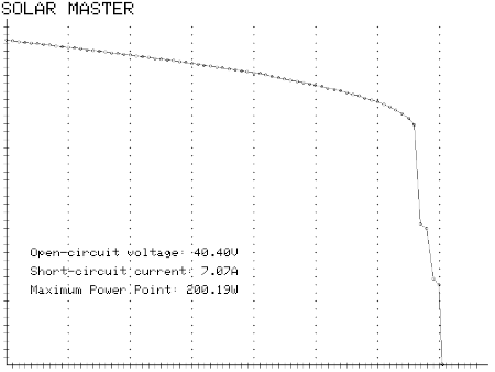
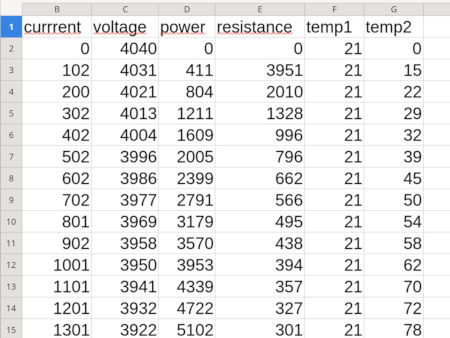
The software measures voltage and current for different loads. It then draws the I-V curve on the e-ink display and calculates the maximum power point. It also saves the data and a graph to the SD card.
BOM
The only information about the load that I could find was from the this EEVblog forum: https://www.eevblog.com/forum/testgear/chinese-electronic-load-500w-module-sousim-500w/. For the load we need a DC power source (12 V, 1 A) and the communication is done via Modbus RTU (Terminal with A+ and B-). This is a differential signal and needs no ground.
- Load from SOUSIM (type14 0-100 V 0-20 A)
- Inkplate 6
- DC-DC step-up breakout board (5 V to 12 V, 1 A)
- MAX485 or EIA232-EIA485 breakout board
Circuit
The circuit is minimal:
URL: https://github.com/e-radionicacom/Croduino-Board-Definitions-for-Arduino-IDE/raw/master/packageCroduinoBoards_index.json Add the URL in the File → Preferences → Additional Board Manager URLs text box. Install libraries (zip files) with: Sketch → Include Lirary → Add .ZIP Library... https://github.com/SolderedElectronics/Inkplate-Arduino-library https://github.com/4-20ma/ModbusMaster
Load
Modbus Address = 1, 9600bit/s
Holding Register 0x03
| 0 | 1 | 0, 1-255 (0x16) | |
| 1 | 1 | 0.CV 1.CC 2.CW 3.CR 4.CV+CC 5. 10. 11-15. | |
| 2 | 0 | 0.OFF 1.ON (100) | |
| 3 | 10000 | CV | Overvoltage (10000 = 100V) |
| 4 | 0 | CC | Current in mA |
| 5 | 0 | CW | Watt |
| 6 | 0 | CR | Resistance |
| 7 | 0 | ||
| 8 | 5 | 5 = 9600 (RS458) | 600,1200,2400,4800,7200,9600,14400,19200,... |
| 9 | 20630 | 120 | Over Current ? 5500 = 55A |
| 10 | 1320 | 120 | |
| 11 | 2000 | 120 | |
| 12 | 1565 | 100 |
INPUT Register 0x04
| 0 | 1 | 0, 1-255 (0x16) | |
| 1 | 1 | 0.CV 1.CC 2.CW 3.CR 4.CV+CC 5. 10. 11-154. | |
| 2 | 0 | 0.OFF 1.ON (100) | |
| 3 | 21 | Temperature in °C | |
| 4 | 0 | Temperature in °C CPU | |
| 5 | 9368 | DVM? | |
| 6 | 4005 | Voltage in mV/10 | |
| 7 | 0 | Current in mA | |
| 8 | 0 | Power | |
| 9 | 0 | Resistance | |
| 10 | 0 | ||
| 11 | 0 | ||
| 12 | 780 | Running Timer in Seconds |
Software
URL: https://github.com/e-radionicacom/Croduino-Board-Definitions-for-Arduino-IDE/raw/master/packageCroduinoBoards_index.json Add the URL in the File → Preferences → Additional Board Manager URLs text box. Install libraries (zip files) with: Sketch → Include Lirary → Add .ZIP Library...
https://github.com/SolderedElectronics/Inkplate-Arduino-library https://github.com/4-20ma/ModbusMaster
Housing
The housing is drawn in FreeCAD. It is not my best design, but it works :). I used PETG instead of PLA because of the heat.
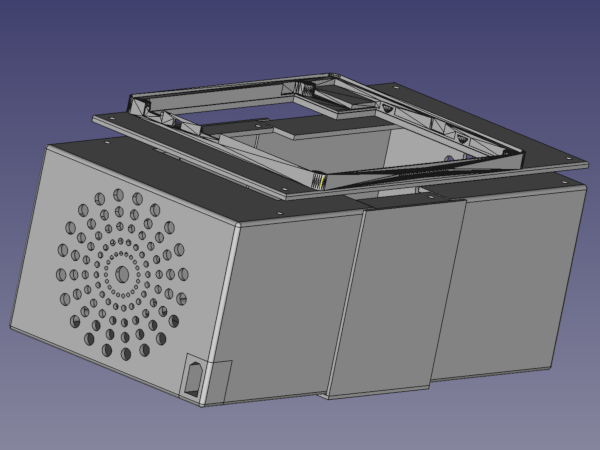
The cover of the inkplate was integrated and can be downloaded here: https://github.com/SolderedElectronics/Inkplate-6-hardware.
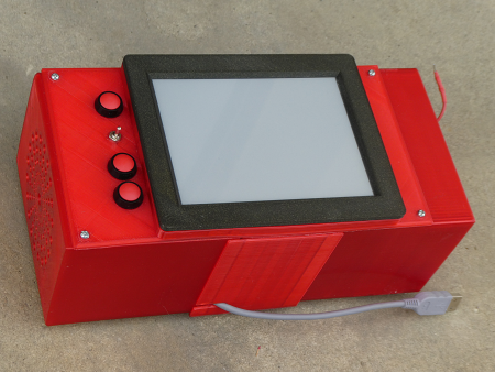
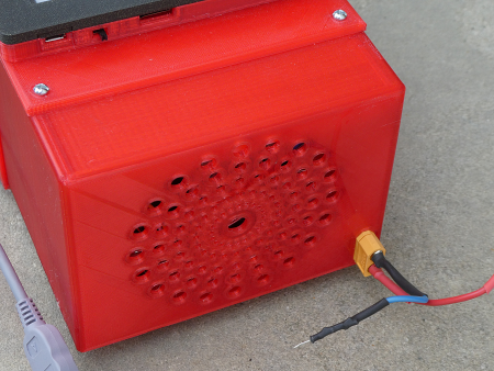
FreeCAD files and stl files are on github.
Problems and To do
The project is working as is, and I don't have the time for the moment to refine the project.
When exposed to the sun for too long the load will heat up and the cooler will run. It is not possible to make use it then, so operate the solar_master in the shadow.
More measure points at the bend in the measurement curve.
- More appealing housing.
Downloads
- Everything on github: https://github.com/weigu1/solar_master
Interesting links
- Inkplate 6: https://soldered.com/product/inkplate-6-6-e-paper-board/
Inkplate 6 hardware: https://github.com/SolderedElectronics/Inkplate-6-hardware
https://github.com/SolderedElectronics/Inkplate-Arduino-library
- https://github.com/4-20ma/ModbusMaster
