Microcontroller projects
last updated: 24/03/19
Convert your AVR experiments board MICES2 to Arduino
Introduction
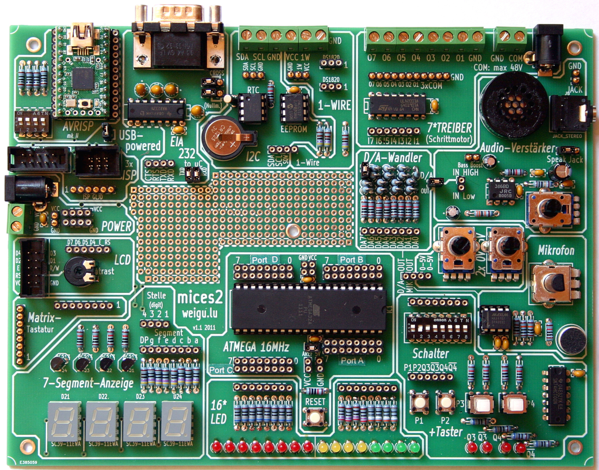
Some years ago I developed a low-cost experiments board for AVR controller, the MICES2 board. It was used by my students to learn AVR assembler. Today Arduino gives us the possibility to use the board without programmer.
Software
First we flash the Arduino bootloader to our ATmega chip. Best use an ATmega644p, so you get a supplementary hardware serial port (PD2, PD3). If you don't need this, you can use the ATmega32.
We are lucky that MCUdude maintains the MightyCore for Arduino. You can find the software on https://github.com/mcudude/MightyCore. To install it in Arduino is not complicated:
- In
File→Preferencesadd the following URL inAdditional Boards Manager URLs:
https://mcudude.github.io/MightyCore/package_MCUdude_MightyCore_index.json
- Separate the URLs using a comma if you have more than one URL.
- Go to
Tools→Board→Boards Manager...and scroll down to MightyCore. - Click on
Installand restart Arduino.
To flash the bootloader, chose the right chip under Tools → Board. The clock is 16MHz external.
Under Tools → Programmer choose AVRISP mkII. Hold the shift key and click on Tools → Burn Bootloader. Now remove the Teensy 2.0 chip.
Hardware
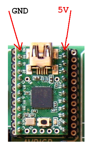
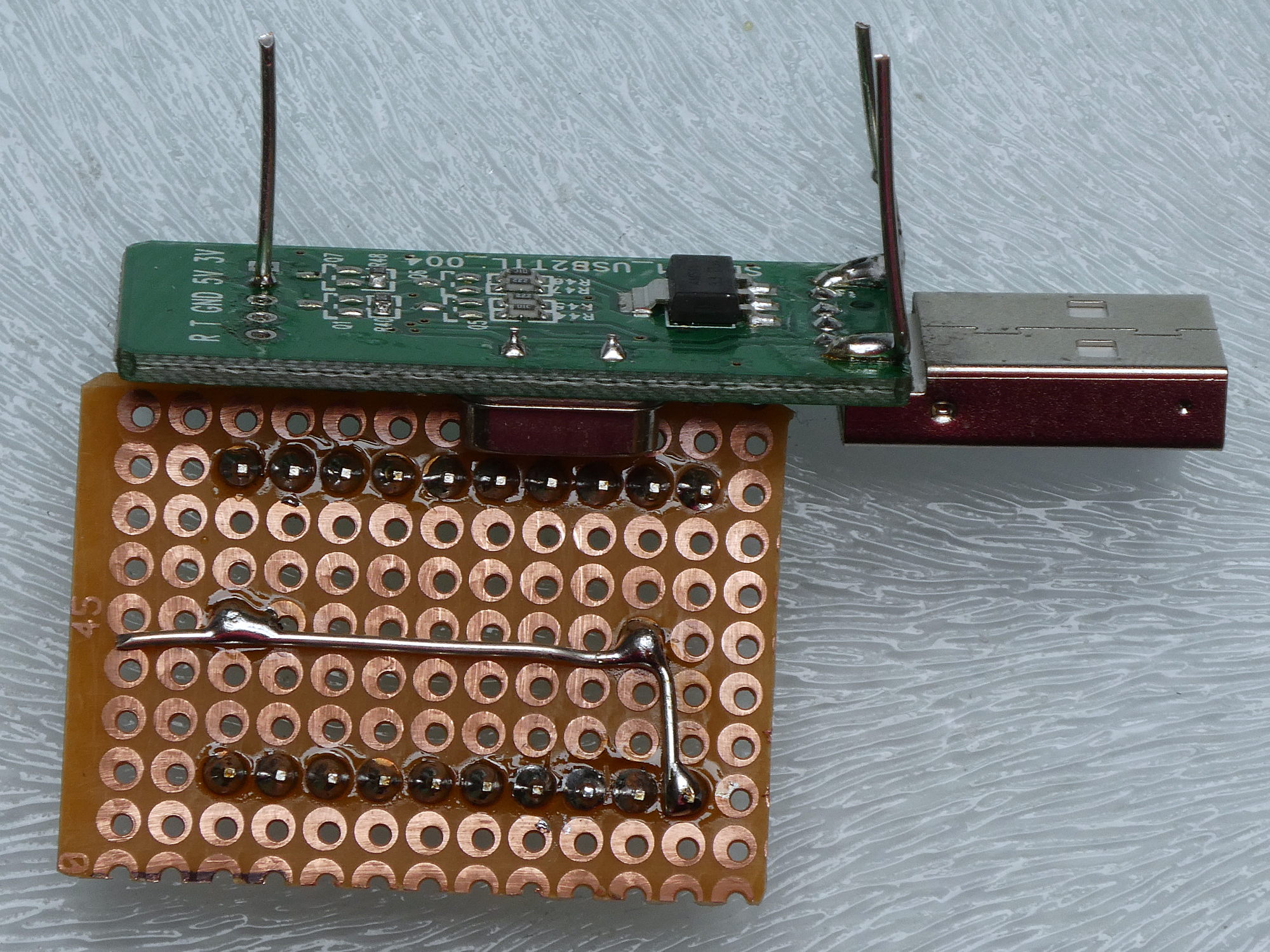
We replace the programmer (Teensy 2.0 as mk2) by an USB2TTL serial converter with CH340G chip. These converters are very cheap (you can also use an adapter with FTDI chip). They often have 4 or 5 pins: Ground, 5V, RxD, TxD and sometimes 3V. Ground and 5 V will be connected to the Teensy pins GND and 5 V, to power the board with 5V from USB.
For this I removed the connector and used a piece of a prototype PCB an soldered the US2TTL board with hard wires (only 5 V and GND) to the PCB and also two rows of pin headers (you can additionally glue the board to the pcb).
RxD will be connected with TxD on the ATmega chip and TxD with RxD. This can be done by using the pin headers on the MICES2 board as shown in the picture. We also need to connect DTR through a 100nF capacitor to Reset. For this we solder the 100 nF cap to Pin 13 of the CH340 chip, glue it to the chip and solder a wire with header to the other side of the cap. This wire is connected to the programming pin header on the board:
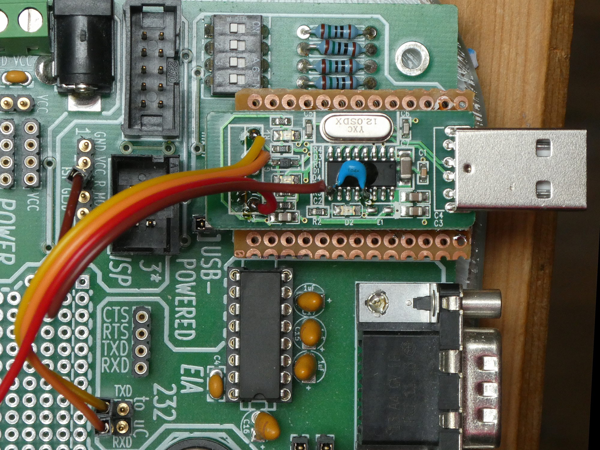
The 3 V output can be used for prototyping and to to power 3 V breakout boards.
MightyCore DIP40 Standard pinout
We select the standard layout in Arduino Tools (default), wich is quite straightforward. The digital pins are numbered from 0-31 beginning with portB (PB0) to portD to portC to portA (PA7).

A better image is found on https://github.com/mcudude/MightyCore.
