Microcontroller projects
SA1200p CO2 hacks
last updated: 2023-06-05
Introduction
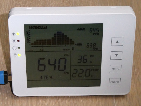
It is important to hack devices to learn things and understand how things work.
All schools in Luxembourg got due to the COVID situation CO2 monitors called SA1200P. They can be purchased in different countries; here some links:
- voelkner.de
- conrad.com
- envisense.co.uk
- [shiantech.en.made-in-china.com]https://shiantech.en.made-in-china.com/product/NyfQqeoCksVG/China-Household-Carbon-Dioxide-Detector-SA1200p-Digital-CO2-Monitor-Indoor-Air-Quality-Monitor-Ce.html
- aliexpress.com
Unfortunately this devices are not produced in Europe, they are not very smart nor IoT, nor are they well suited to use in a classroom. So let's change this and get them at least smarter :).
The hacks
First we look at the hardware to understand with what we are dealing here:
Hardware hack
A first inspection of the PCB.ESP8266 hack
add an ESP8266 to get WiFi connectivity and the possibility to add other sensors and LoRa.Getting the firmware
Yes, the firmware is not secured.Digging deeper in hardware
Analysing all the hardware in deep.Adding Serial over USB
Writing our own program on the STM32L152 µC.
Hardware hack
A first inspection shows that the PCB is not fully populated and only very few components are used:
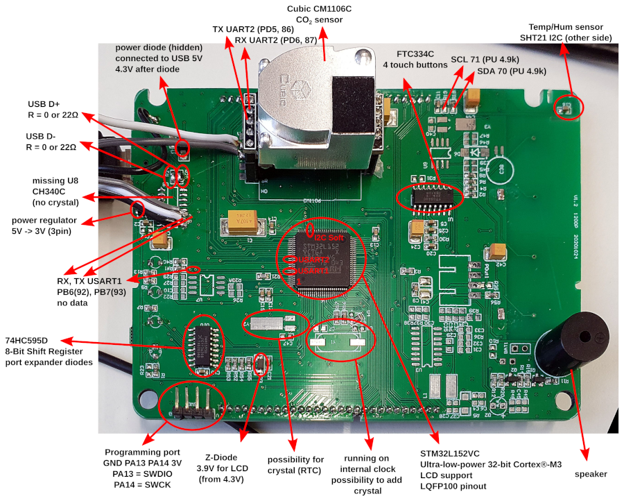
BOM
- STM32L152VCT6A (www.st.com) ultra-low-power 32-bit MCU ARM®-based Cortex®-M3 (LQFP100 pinout)
- LCD Display driven by the µC.
- Cubic CM1106C CO2 sensor. Serial interface (9600 bit/s, 8N1).
- Sensirion SHT21 Temperature and humidity sensor I2C interface. Connected to software bus (15 kHz).
- 74HC595D 8 bit shift-register for 4 LEDs
- FTC334C for 4 touch buttons
- Piezo speaker
ESP8266 hack
Adding an ESP8266 to get WiFi connectivity and the possibility to add other sensors and LoRa.
WiFi with ESP8266
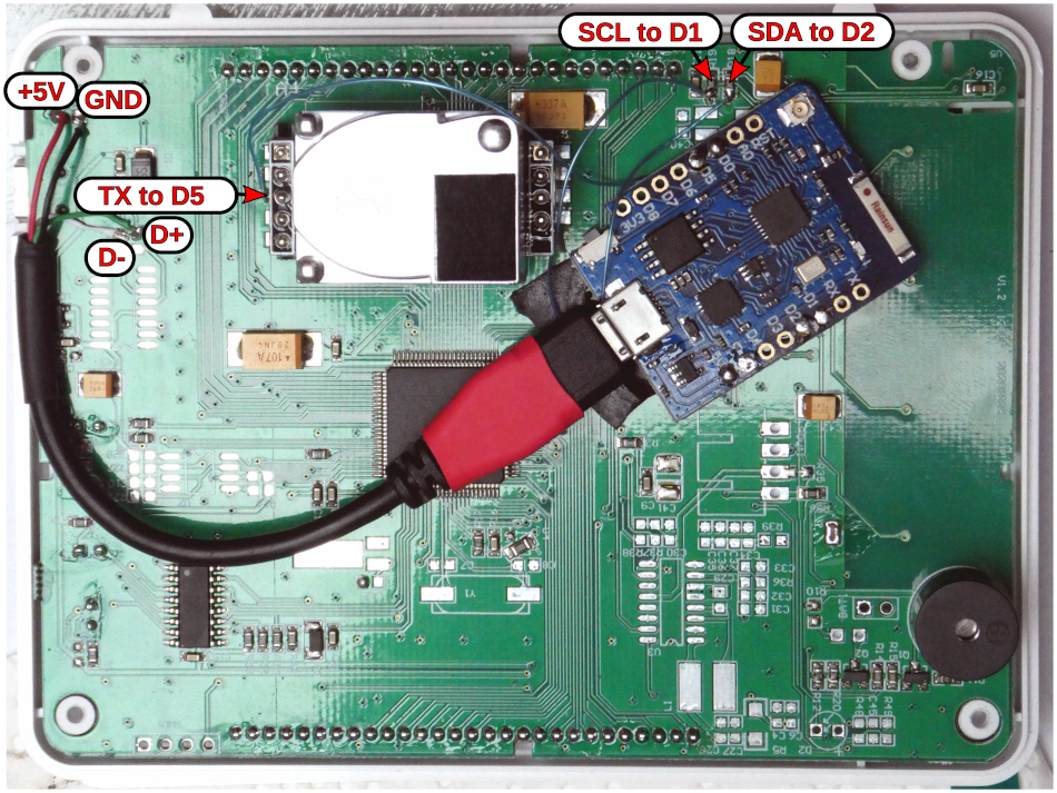
So clearly we need something to get the data out of the device. I choose the beloved WEMOS D1 mini pro (ESP8266) with WiFi. As we get idle pads for the USB data lines (D+, D-) we can connect the board directly to the Mini USB connector. So it is powered and we are able to reprogram the ESP even with a closed housing.
CO2
To get the data from the CO2 sensor is the easy part. I use the ESP softserial library with pin D5. Hardware RX is no good choice because it is used when uploading a sketch. Softserial gives here no problems because the bit-rate is only at 9600 bit/s (8N1). The data begins with a start byte (µC Tx 0x11, Rx from sensor 0x16), followed by the length of the frame bytes (command + data) (µC Tx 0x01, Rx from sensor 0x05), the command (Tx and Rx: 0x01), the data (µC Tx no data, Rx from sensor 4 byte) and a checksum byte.
The checksum is calculated as cumulative sum of data = 256-(HEAD+LEN+CMD+DATA)%256.
The 4 bytes send by the µC to get the data are: 0x11,0x01,0x01,0xED (data sheet page 9).
We get 8 bytes back from the sensor, and these bytes are sniffed. The three first bytes are 0x16,0x05,0x01. Then we get the 4 data bytes and the checksum.
The CO2 measured result in ppm is calculated with the two firs data bytes: first byte*256 + second byte. The other two bytes are not needed (reserved).
Temperature and humidity
To sniff on an I2C or TWI bus is more challenging. It can be done using an interrupt on the clock line and a little bit bit fiddeling :). Fortunately the master uses a software interface with only 15 kHz. In the net we read that the ESP8266 is, because of the RTOS quite slow on the interrupts. 100 kHz, the normal clock speed of I2C, could be too fast.
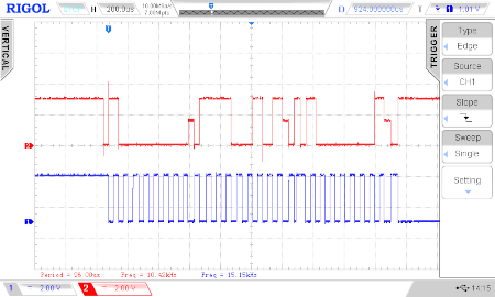
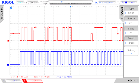
The master asks, after sending the address (0x40) + write bit (0, 0x80) by sending the command 0xE5 for the humidity. The third byte is the address + read byte (1, 0x81). The slaves ACK bits are only 1.5 V.
Left screen: 0x80 + ACK + 0xE5 + ACK + 0x81 + ACK (2 ms).
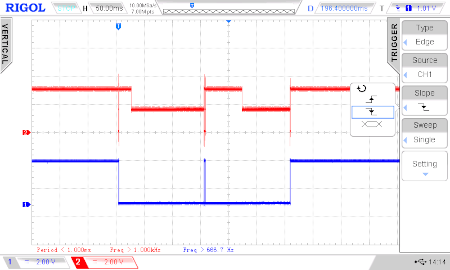
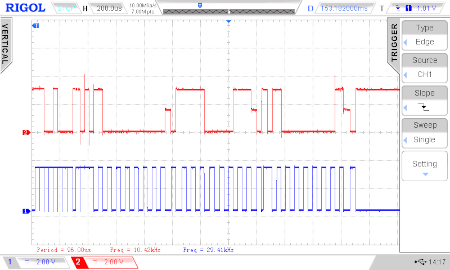
The sensor uses a halt mechanism (hold master) when converting the data, as we can see in the right screen (other time scale!). The clock line (blue) is pulled to GND after the first 3 byte (only visible as falling edge) for 150 ms to get the humidity. In the middle we have 3 byte answer and 3 byte where the master asks for the temperature and then again 150 ms before the 3 byte answer:
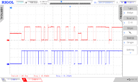
The next two screens show the humidity answer (MSB 0x58 + ACK + LSB 0x82 + ACK + CRC 0xC8 + ACK) and the master asking for the temperature (0x80 + ACK + 0xE3 + ACK + 0x81 + ACK (2 ms).)
Finally we get the answer for the temperature (MSB 0x66 + ACK + LSB 0xA4 + ACK + CRC 0x37 + ACK)
Soldering
We connect SDA with D2, SCL with D1 and serial TX with D5. These pins can be changed if needed in software.
Software
Our software can send CO2, temperature and humidity values over WiFi to an MQTT server.
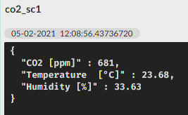
For more infos about MQTT look here: http://weigu.lu/tutorials/sensors2bus/06_mqtt/index.html
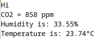
Here the code of a version without WiFi and MQTT, which is not so overloaded with information. We get the data over USB, and can view the data in the Serial Monitor of the Arduino IDE. The other version is in "Downloads" (end of the page). With Arduino we can
    // sa1200p_with_esp_no_wifi.ino
    // weigu.lu

    #include <SoftwareSerial.h>

    //#define DEBUG

    const byte CO2_RX = 14; // D5
    const byte SDA_PIN = 4; // D2
    const byte SCL_PIN = 5; // D1
    byte event_counter = 0;
    int co2;
    float sht21_value;
    float hum, temp;
    const byte buffer_bytes = 8;
    volatile byte bit_buffer[buffer_bytes];
    volatile byte bit_counter = 0;

    SoftwareSerial SerialCO2(CO2_RX); // RX

    void setup() {
      pinMode(SDA_PIN,INPUT);
      pinMode(SCL_PIN,INPUT);
      Serial.begin(115200);
      SerialCO2.begin(9600);
      delay(500);
      Serial.println("Hi");
      attachInterrupt(digitalPinToInterrupt(SCL_PIN), isr_scl, RISING);
      noInterrupts();
      clear_buffer(buffer_bytes);
      bit_counter = 0;
      interrupts(); // allow interrupts
    }

    void loop() {
      if (SerialCO2.available()) {
        co2 = get_CO2();
        if (co2 == -1) {
          Serial.println("Serial data (co2) corrupt");
        }
        else {
          Serial.println("CO2 = " + String(co2) + " ppm");
        }
      }
      sht21_value = get_sht21_data();
      if ((event_counter == 2) && (sht21_value > 0.0)) {
        hum = sht21_value;
        Serial.println("Humidity is: " + String(hum) + "%");
      }
      else if ((event_counter == 3) && (sht21_value > 0.0)) {
        temp = sht21_value;
        Serial.println("Temperature is: " + String(temp) + "°C");
        event_counter = 0;
      }
      else if ((sht21_value == -1)) {
        Serial.println("SHT21 CRC error");
      }

      delay(100);
      yield();
    }

    ICACHE_RAM_ATTR void isr_scl() {
      //delayMicroseconds(15);
      if (digitalRead(SDA_PIN)) {
        bitSet(bit_buffer[bit_counter/8], 7-bit_counter%8);
      }
      else {
        bitClear(bit_buffer[bit_counter/8], 7-bit_counter%8);
      }
      bit_counter++;
    }

    //clear buffer
    void clear_buffer(byte lbuffer_bytes) {
      for (byte i=0; i<lbuffer_bytes; i++) {
        bit_buffer[i]=0;
      }
    }

    // get the CO2 data
    int get_CO2() {
      int co2_lvalue;
      byte co2_byte_counter = 0, co2_data[10], co2_checksum;
      while (SerialCO2.available()) {
        co2_data[co2_byte_counter] = SerialCO2.read();
        co2_byte_counter++;
      }
      // are the three first byte ok?
      if ((co2_data[0] != 0x16) || (co2_data[1] != 0x05) || (co2_data[2] != 0x01)) {
        #ifdef DEBUG
          Serial.println("data corrupt");
        #endif
        return -1;
      }
      // calculate the checksum and test if ok
      co2_checksum = 0;
      for (byte i=0; i<co2_byte_counter-1; i++) {
        co2_checksum += co2_data[i];
      }
      co2_checksum = 256-co2_checksum;
      if (co2_data[co2_byte_counter-1]!=co2_checksum) {
        #ifdef DEBUG
          Serial.println("Checksum not ok");
        #endif
        return -1;
      }
      co2_lvalue = co2_data[3]*256+co2_data[4];
      #ifdef DEBUG
        for (byte i=0; i<co2_byte_counter; i++) {
          Serial.print(co2_data[i],HEX);
          Serial.print(' ');
        }
        Serial.print(" checksum: " + String(co2_checksum,HEX));
      #endif
      for (byte i=0; i<sizeof(co2_data); i++) { //clear buffer
        co2_data[i]=0;
      }
      co2_byte_counter = 0;
      return co2_lvalue;
    }

    // we need global vars bit_counter, bitbuffer, envent_counter
    float get_sht21_data() {
      byte msb, lsb, crc;
      unsigned int data_word = 0;
      float lhum, ltemp;
      if (bit_counter >= 28) {
        delay(2); //wait 2ms for the other bits
        noInterrupts();
        if (bit_buffer[0]==0x80) { // master
          event_counter = 1;
        }
        else if (event_counter == 1) { // hum data from slave
          msb = bit_buffer[0];
          lsb = bit_buffer[1] << 1;    // eliminate ACK bits
          crc = bit_buffer[2] << 2;
          lsb = lsb + (bit_buffer[2] >> 7);
          crc = crc + (bit_buffer[3] >> 6);
          if (check_crc(msb, lsb, crc) == false) {
            event_counter = 0;
            return -1;
          }
          lsb &= 0xFC;                 // clear last 2 bits (data sheet)
          data_word = msb*256+lsb;
          lhum = -6.0+(125.0*data_word/65536.0);
          check_crc(0x66, 0xA4, 0x37);
          #ifdef DEBUG
            Serial.print("msb: " + String(msb,HEX) + " lsb: " + String(lsb,HEX));
            Serial.println(" crc: " + String(crc,HEX) + " data word: " + String(data_word));
          #endif
          event_counter = 2;
        }
        else if (event_counter == 2) { // temp data from slave
                msb = bit_buffer[0];
          lsb = bit_buffer[1] << 1;    // eliminate ACK bits
          crc = bit_buffer[2] << 2;
          lsb = lsb + (bit_buffer[2] >> 7);
          crc = crc + (bit_buffer[3] >> 6);
          if (check_crc(msb, lsb, crc) == false) {
            event_counter = 0;
            return -1;
          }
          lsb &= 0xFC;                 // clear last 2 bits (data sheet)
          data_word = msb*256+lsb;
          ltemp = -46.85+(175.72*data_word/65536.0);
          ltemp = ltemp -1.65;          // correction for housing error?
          #ifdef DEBUG
            Serial.print("msb: " + String(msb,HEX) + " lsb: " + String(lsb,HEX));
            Serial.println(" crc: " + String(crc,HEX) + " data word: " + String(data_word));
          #endif
          event_counter = 3;
        }
        #ifdef DEBUG
          Serial.print(String(event_counter) + ":  " + String(bit_counter) + " bit:  ");
          for (byte i=0; i<buffer_bytes; i++) {
            Serial.print(bit_buffer[i],HEX);
            Serial.print('\t');
          }
          delay(10);
          Serial.println();
        #endif
        clear_buffer(buffer_bytes);
        bit_counter = 0;
        interrupts();
        if (event_counter == 2) {
          return lhum;
        }
        else if (event_counter == 3) {
          return ltemp;
        }
      }
    }

    // from Sensiron application note and code
    bool check_crc(byte lmsb, byte llsb, byte lcrc) {
      byte bitmask;
      byte calc_crc = 0x00; // initial value as per Table 17
      calc_crc ^= (lmsb); // do msb
      for (bitmask = 8; bitmask > 0; --bitmask)  {
        if (calc_crc & 0x80) {
          calc_crc = (calc_crc << 1) ^ 0x131;
        }
        else {
          calc_crc = (calc_crc << 1);
        }
      }
      calc_crc ^= (llsb); // do lsb
      for (bitmask = 8; bitmask > 0; --bitmask)  {
        if (calc_crc & 0x80) {
          calc_crc = (calc_crc << 1) ^ 0x131; // polynomial from Table 17
        }
        else {
          calc_crc = (calc_crc << 1);
        }
      }
      #ifdef DEBUG
        Serial.println("------------------");
        Serial.print("msb: " + String(lmsb,HEX) + " lsb: " + String(llsb,HEX));
        Serial.println(" crc: " + String(lcrc,HEX) + ""  calculated checksum = " + String(calc_crc,HEX));
        Serial.println("------------------");
      #endif
      if (calc_crc != lcrc) {
        return false;     // checksum error
      }
      else {
        return true;      // no error
      }
    }
Getting the firmware
Now let's see if the firmware is locked.
To get the original firmware we use the STM32CubeProgrammer software from www.st.com that is free and runs also under Linux. We need an ST-LINK/V2 programmer. Fortunately they are cheap and the best way is to buy a Nucleo board where the programmers are integrated. We connect the ST-Link header with the programming header SWD1 on the mainboard (GND (G), SWDIO, SWCK, 3V(V)).
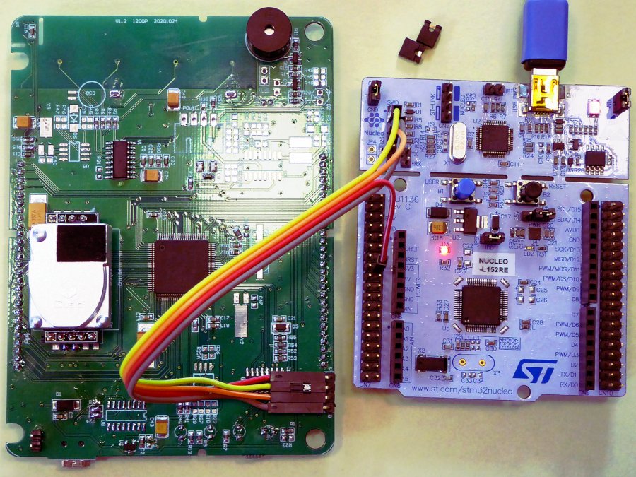
As we can see in the picture we need to remove the two jumpers (ST-Link) as we want to program an external board. The data (SWDIO) is on pin 2 of the ST-Link header, clock (SWCK) on pin 4 and GND in the middle (pin3)) We find the 3 V to power the board near the Arduino header.
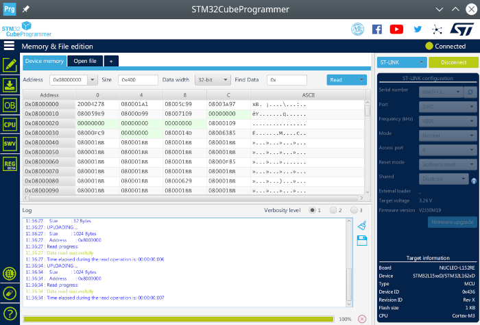
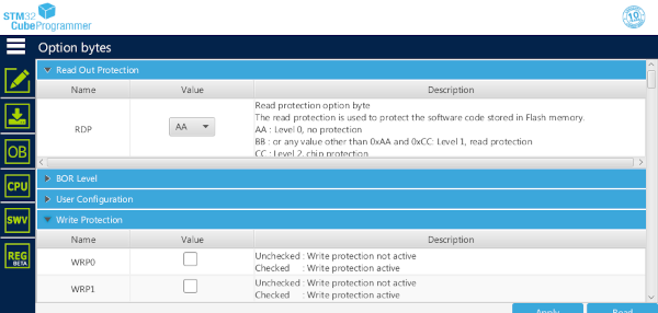
Now we open the software and click on Connect (top right)) in the software and see the content of the Flash in our window. The firmware is not locked as we can see in the !
Digging deeper in hardware
Analysing all the hardware in deep. First the one hundred STM32L152VC-A pins :)
| Pin Nr | Connected to: | Portpin | other mapping | Pin Nr | Connected to: | Portpin | other mapping | |
|---|---|---|---|---|---|---|---|---|
| 001 | LCD47 | PE2 | 051 | LCD21 | PB12 | |||
| 002 | NC? | PE3 | 052 | LCD22 | PB13 | |||
| 003 | HC595 SERCLK (11) | PE4 | 053 | LCD23 | PB14 | |||
| 004 | HC595 SER (14) | PE5 | 054 | LCD24 | PB15 | |||
| 005 | HC595 RCLK (12) | PE6 | WKUP3 | 055 | LCD37 | PD8 | ||
| 006 | 3.9 V Z-Diode from 4.3 V | VLCD | 056 | LCD38 | PD9 | |||
| 007 | NC? | PC13 | WKUP2 | 057 | LCD39 | PD10 | ||
| 008 | crystal Y2 (32.768 kHz) | PC14 | OSC32_IN | 058 | LCD40 | PD11 | ||
| 009 | crystal Y2 (32.768 kHz) | PC15 | OSC32_OUT | 059 | LCD41 | PD12 | ||
| 010 | GND | VSS_5 | 060 | LCD42 | PB13 | |||
| 011 | 3.0 V | VDD_5 | 061 | LCD43 | PB14 | |||
| 012 | crystal Y1 | PH0 | OSC_IN | 062 | LCD44 | PB15 | ||
| 013 | crystal Y1 | PH1 | OSC_OUT | 063 | LCD33 | PC6 | ||
| 014 | R17+100k PU | NRST | external Reset | 064 | LCD34 | PC7 | ||
| 015 | LCD27 | PC0 | 065 | LCD35 | PC8 | |||
| 016 | LCD28 | PC1 | 066 | LCD36 | PC9 | |||
| 017 | LCD29 | PC2 | 067 | LCD48 | PA8 | |||
| 018 | LCD30 | PC3 | 068 | LCD49 | PA9 | |||
| 019 | GND | VSSA | 069 | LCD50 | PA10 | |||
| 020 | GND | VREF- | 070 | SDA Soft? | PA11 | |||
| 021 | 3.0 V | VREF+ | 071 | SCL Soft? | PA12 | |||
| 022 | 3.0 V | VDDA | 072 | SWD1: SWDIO | PA13 | |||
| 023 | NC? | PA0 | WKUP1 | 073 | R1 Piezo? | PH2 | ||
| 024 | LCD09 | PA1 | 074 | GND | VSS_2 | |||
| 025 | LCD10 | PA2 | 075 | 3.0 V | VDD_2 | |||
| 026 | LCD11 | PA3 | 076 | SWD1: SWCLK | PA14 | |||
| 027 | GND | VSS_4 | 077 | PA15 | ||||
| 028 | 3.0 V | VDD_4 | 078 | LCD52 | PC10 | |||
| 029 | PA4 | 079 | LCD53 | PC11 | ||||
| 030 | U3 (9) | PA5 | 080 | LCD54 | PC12 | |||
| 031 | LCD12 | PA6 | 081 | U7 (1) (SPI2_NSS) | PD0 | |||
| 032 | LCD13 | PA7 | 082 | U7 (6) (SPI2_SCK) | PD1 | |||
| 033 | LCD31 | PC4 | 083 | LCD55 | PD2 | |||
| 034 | LCD32 | PC5 | 084 | U7 (2) (SPI2_MISO) | PD3 | |||
| 035 | LCD14 | PB0 | 085 | U7 (5) (SPI2_MOSI) | PD4 | |||
| 036 | LCD15 | PB1 | 086 | Tx USART2 | PD5 | |||
| 037 | U3 (15) | PB2 | 087 | Rx USART2 | PD6 | |||
| 038 | PE7 | 088 | PD7 | |||||
| 039 | PE8 | 089 | PB3 | |||||
| 040 | PE9 | 090 | PB4 | |||||
| 041 | PE10 | 091 | PB5 | |||||
| 042 | PE11 | 092 | Rx USART1 | PB6 | ||||
| 043 | U1 (13) | PE12 | 093 | Tx USART1 | PB7 | |||
| 044 | U1 (14) | PE13 | 094 | BOOT0 | ||||
| 045 | U1 (15) | PE14 | 095 | PB8 | ||||
| 046 | U1 (16) | PE15 | 096 | LCD 51 | PB9 | |||
| 047 | LCD19 | PB10 | 097 | LCD 45 | PE0 | |||
| 048 | LCD20 | PB11 | 098 | LCD 46 | PE1 | |||
| 049 | GND | VSS_1 | 099 | GND | VSS_3 | |||
| 050 | 3.0 V | VDD_1 | 100 | 3.0 V | VDD_3 |
4 LEDs
To access the 4 LEDs a shift register SIPO 74HC595D is used. More on shift register: http://weigu.lu/tutorials/microcontroller/03_sequential_logic/index.html.
| PIN | PIN | |||||
|---|---|---|---|---|---|---|
| 01 | QB | connected but where? | 09 | QH' | NC | |
| 02 | QC | 10 | /SRCLR | +4.7 V | ||
| 03 | QD | GREEN(top) - R1(350) - VDD | 11 | SRCLK | STM32-3 | |
| 04 | QE | RED(top) - R7(1.5k) - VDD | 12 | RCLK | STM32-5 | |
| 05 | QF | YELLOW(top) - R9(1.5k) - VDD | 13 | /OE | GND | |
| 06 | QG | GREEN(botom) - R13(350) - VDD | 14 | SER | STM32-4 | |
| 07 | QH | connected but where? | 15 | QA | R12 PIEZO? | |
| 08 | GND | GND | 16 | VDD | +4.7 V |
SPI Flash (U7)
By examining the pins of U7 I saw that space is reserved for an SPI Flash chip as described here.
We can use if needed an SPI flash part numbers starting with "MX25" or "W25" or "AT25" or "SST25" etc. The first two letters are the manufacturer name.
| PIN | PIN | |||||
|---|---|---|---|---|---|---|
| 01 | SPI2_NSS | STM32-81 | 05 | SPI2_MOSI | STM32-85 | |
| 02 | SPI2_MISO | STM32-84 | 06 | SPI2_SCK | STM32-82 | |
| 03 | WP# | 07 | HOLD# | |||
| 04 | GND | 08 | VCC |
Adding Serial over USB]
Writing our own program on the STM32L152 µC.
Programming without debugging over a serial port (USART) is no fun. So the first step is to add a serial port. In our hardware analyses we found that USB is not connected to USART1. Let's change this. I bought an CH340C (the C version has an internal oscillator!) chip and soldered it to the PCB (U8). D+ and D- are connected adding R24 and R25 (0 Ω , or 22 Ω).
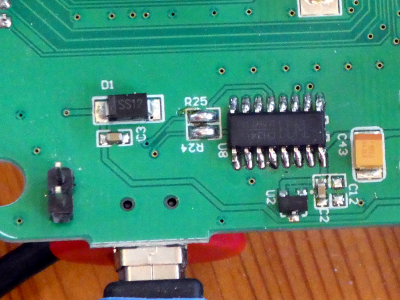
Now we can use USART1 (115200bit/s 8N1) to debug over USB. USART2 (9600bit/s 8N1) is needed to get the CO2 data. So let's write a program to send CO2 data to USB. First initialise the Pins as described here: http://weigu.lu/microcontroller/stm32/index.html (end of the page).
Than we add the code:
First the header.file (copy to Inc):
    /* serial_hal.h  Author: weigu.lu */

    #ifndef INC_SERIAL_HAL_H_
    #define INC_SERIAL_HAL_H_

    #include "main.h"
    #include "string.h"

    UART_HandleTypeDef huart1;
    UART_HandleTypeDef huart2;

    void serial1_send_ascii(char buffer[]);
    void serial1_send_bin(uint8_t* buffer, uint8_t length);
    void serial1_send_int(int i);

    #endif /* INC_SERIAL_HAL_H_ */
and c-file (copy to Src) with some basic functions:
    /* serial_hal.c  Author: weigu.lu */

    #include <stdio.h> // for sprintf
    #include "main.h"
    #include "serial_hal.h"

    void serial1_send_ascii(char buffer[]) {
        if (HAL_UART_Transmit(&huart1, (uint8_t*) buffer, strlen(buffer), HAL_MAX_DELAY) != HAL_OK) {
            Error_Handler();
        }
    }
    void serial1_send_bin(uint8_t* buffer, uint8_t length) {
        if (HAL_UART_Transmit(&huart1, buffer, length, HAL_MAX_DELAY) != HAL_OK) {
            Error_Handler();
        }
    }
    void serial1_send_int(int i) {
        char buffer[8];
        sprintf(buffer, "%d", i);
        if (HAL_UART_Transmit(&huart1, (uint8_t*)buffer, strlen(buffer), HAL_MAX_DELAY) != HAL_OK) {
            Error_Handler();
        }
    }
And here some code for main.c
    #include "serial_hal.h"

    // Read measured result CO2
    // sending: start(0x11),length(0x01),command(0x01),checksum(0xED)
    // answer: 0x16,length(5),0x01,DF1-DF4,checksum(1byte)
    int serial2_get_co2() {
        int co2_lvalue;
        uint8_t co2_checksum;
        uint8_t co2_data[10] = {0};
        uint8_t uart2_tx_buffer[] = {0x11,0x01,0x01,0xED}; // data sheet
        if (HAL_UART_Transmit(&huart2, uart2_tx_buffer, 4, HAL_MAX_DELAY) != HAL_OK) {
            Error_Handler();
        }
        HAL_UART_Receive (&huart2, co2_data, 10, 5000);
        /*#ifdef DEBUG
            serial1_send_bin(uart2_tx_buffer,4); // debug
            serial1_send_bin(co2_data,10); // debug
        #endif*/
        // are the three first byte ok?
        if ((co2_data[0] != 0x16) || (co2_data[1] != 0x05) || (co2_data[2] != 0x01)) {
            #ifdef DEBUG
                serial1_send_ascii("data corrupt\n");
            #endif
            return -1;
        }
        // calculate the checksum and test if ok
        co2_checksum = 0;
        for (uint8_t i=0; i<7; i++) {
            co2_checksum += co2_data[i];
        }
        co2_checksum = 256-co2_checksum;
        if (co2_data[7]!=co2_checksum) {
            #ifdef DEBUG
                serial1_send_ascii("Checksum not ok\n");
            #endif
            return -1;
        }
        // calculate the CO2 value and clear the buffer
        co2_lvalue = co2_data[3]*256+co2_data[4];
        for (uint8_t i=0; i<sizeof(co2_data); i++) { //clear buffer
            co2_data[i]=0;
        }
        return co2_lvalue;
    }

    int main(void) {
      /* Initialize all configured peripherals */
      MX_GPIO_Init();
      MX_USART1_UART_Init();
      MX_USART2_UART_Init();
      /* USER CODE BEGIN 2 */
      serial1_send_ascii("Hello Serial\n");
      /* USER CODE END 2 */
      while (1)  {
          //HAL_GPIO_TogglePin(GPIOD,GPIO_PIN_0);
          int j = serial2_get_co2();
          serial1_send_ascii("CO2 = ");
          serial1_send_int(j);
          serial1_send_ascii(" ppm\n");
          HAL_Delay(1000);
        /* USER CODE END WHILE */
    }
Now we get our CO2 data over USB.
Closing claim
I will not pursue with programming my own firmware on this chip. The main problem is that I didn't find easily cool libraries to help while programming. Rewriting all functions for Serial, Software I2C, integrated LCD and LoRa chips it is too time consuming.
Downloads
- sa1200p_with_esp_no_wifi.ino
- sa1200p_with_esp_wifi.zip (unzip the file to your Sketchbook folder and open the ino file)
- enhanced software MQTT-CO2.zip by Robert Fisch (unzip the file to your Sketchbook folder and open the ino file)
Links
