Microcontroller projects
LoRa P2P with ESP8266 or ESP32 and the SX1276 from SEMTECH
last updated: 2024-03-02
Quick links
Intro
LoRa was developped by SEMTECH. We will use here their simple LoRa chip SX1276, that can be bought on a breakout board RFM95W-V2.0 from hoperf). With an ESP8266 (WEMOS D1 mini (pro) or an ESP32 (MHETLIVE Minikit) and the LoRa library from Sandeep Mistry it is easy to build a LoRa p2p device.
Hardware
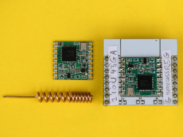
Unfortunately the breakout board RFM95W uses a 2 mm pin header pitch instead of the usually used 2.54 mm (0.1 in). So we need an additional breakout board to be able to use the chip on a breadboard.
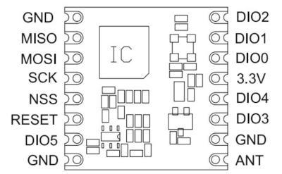
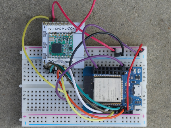
Connections:
Don't forget to connect the antenna before powering the board! Without antenna the board can be damaged!
If you don't have an antenna, use a wire with 8.2 cm in length.
The board uses the SPI interface (MISO, MOSI, SCK, SS (NSS)) to communicate with the microcontroller, and it is powered with 3.3 V (GND, +3.3 V).
For SPI we usually use the pins of the default SPI interface for MISO, MOSI and SCK. With the function SPI.begin() it is possible to change if a second interface is available. The chip select pin is freely selectable. The library uses by default pin 5. The DI00 pin (RFM95W) must be connected to a pin supporting interrupts, because the LoRa chip signals an incoming message with this output to the microcontroller (default pin 2). Same for DI01, needed only for LoRaWAN (default pin 6). An output pin of the microcontroller can also be used to reset (RESET pin) the LoRa chip if needed.
| LoRa board | Arduino Uno (3V!) | ESP8266 (WEMOS) | ESP32 (MHETLIVE Minikit) |
|---|---|---|---|
| 3.3V (Vin) | 3.3V | 3.3V | 3.3V |
| GND | GND | GND | GND |
| MOSI | 11 | 14 | 23 |
| MISO | 12 | 12 | 19 |
| SCK | 13 | 13 | 18 |
| NSS (SS, CS) | 5 | 16 | 5 |
| RST (Reset) | 9 | not connected | not connected |
| DIO0 (G0, IRQ) | 2 | 15 | 26 |
| DIO1 (G1, IRQ) | 6 (only needed for LoRaWAN!) | (only needed for LoRaWAN!) | (only needed for LoRaWAN!) |
| DIO2-5 | not connected | not connected | not connected |
| ANT | antenna | antenna | antenna |
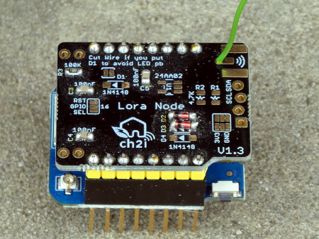
On the net I found an interesting PCB from Charles-Henri Hallard (CH2i) and ordered some PCBs. The version is 1.3. I populated them with only the most necessary components:
RFM95 LoRa breakout, DIO0, DIO1 (only if we need LoRaWAN), C1 (1µF), C2(10µF), R3 (100k).
They work both wit the ESP8266 (WEMOS D1 mini) and the ESP32 (MHETLIVE Minikit) with the same connections as above.
The same connections are also used for the SmartyReader® board v2.2.
Software
We use the LoRa library from Sandeep Mistry. Information about the library can be found in the corresponding LoRa Application Programming Interface (API).
The software can be found on github: https://github.com/weigu1/lora_p2p_SX1276_esp.
Here are two basic sketches for the sender (transmitter):
Sender
    /*
      lora_p2p_esp_sx1276_simple_sender_868.ino

      weigu.lu 2024

      ESP32:   MH ET LIVE ESP32-MINI-KIT  with RFM95W (SX1276)
      ESP8266: WEMOS D1 mini pro with RFM95W (SX1276)

          MH ET Live   |---|   Mini Kit              WEMOS |---| D1 Mini Pro

      GND    |  RST    |---|  3 RxD  |    GND        RST         |---|       TxD
       NC    |  SVP 36 |---|  1 TxD  | 27                 A0     |---|       RxD
      SVN 39 |      26 |---| 22 SCL  | 25                 D0 16  |---|  5 D1 SCL
          35 |  SCK 18 |---| 21 SDA  | 32             SCK D5 14  |---|  4 D2 SDA
          33 | MISO 19 |---| 17 TxD2 | 12 TDI        MISO D6 12  |---|  0 D3
          34 | MOSI 23 |---| 16 RxD2 |  4            MOSI D7 13  |---|  2 D4 LED
      TMS 14 |   SS  5 |---|    GND  |  0              SS D8 15  |---|       GND
       NC    |  3V3    |---|    5V   |  2            3V3         |---|        5V
      SD2  9 |  TCK 13 |---| 15 TD0  |  8 SD1
      CMD 11 |  SD3 10 |---|  7 SD0  |  6 CLK

      LoRa board     | ESP8266  | ESP32 |
      3.3V (Vin)     | 3.3V     | 3.3V
      GND            | GND      | GND
      MOSI           | 14       | 23
      MISO           | 12       | 19
      SCK            | 13       | 18
      NSS (SS, CS)   | 16       | 5
      RST (Reset)    | nc       | 33
      DIO0 (G0, IRQ) | 15       | 26
      DIO1 (G1, IRQ) | only WAN | only needed for LoRaWAN!
      DIO2-5         | nc       | not connected (nc)
      ANT            | antenna  | antenna

      freq = 868MHz, SPI pins are default pins MOSI=13/23, MISO=12/19, SCK=14/18
    */

    #include <SPI.h>
    #include <LoRa.h>

    #ifdef ESP8266
      const byte PIN_SS =  16;    // LoRa radio chip select
      const byte PIN_RST = -1;    // LoRa radio reset (not connected)
      const byte PIN_IRQ = 15;    // hardware interrupt pin!
    #else
      const byte PIN_SS =  26;
      const byte PIN_RST = -1;
      const byte PIN_IRQ =  5;
    #endif // #ifdef ESP8266

    //const byte PIN_SCK =  18;
    //const byte PIN_MISO = 19;
    //const byte PIN_MOSI = 23;


    unsigned int counter = 0;

    void setup() {
      Serial.begin(115200);
      Serial.println("LoRa sender\n");
      //SPI.begin(PIN_SCK, PIN_MISO, PIN_MOSI, PIN_SS); // if not default pins
      LoRa.setPins(PIN_SS, PIN_RST, PIN_IRQ);           // setup LoRa transceiver
      if (!LoRa.begin(868E6)) {
        Serial.println("Error starting LoRa!");
        while (true);                                   // endless loop
      }
    }

    void loop() {
      Serial.print("Sending packet number: ");
      Serial.println(counter);
      LoRa.beginPacket();
      LoRa.print("This is packet number ");
      LoRa.print(counter);
      LoRa.endPacket();
      counter++;
      delay(60000);
    }
Receiver (polling)
    /*
      lora_p2p_esp_sx1276_simple_receiver_868.ino

      The receiver uses polling. Look at the transceiver example for callback.
    */

    #include <SPI.h>
    #include <LoRa.h>

    #ifdef ESP8266
      const byte PIN_SS =  16;    // LoRa radio chip select
      const byte PIN_RST = -1;    // LoRa radio reset (not connected)
      const byte PIN_IRQ = 15;   // hardware interrupt pin!
    #else
      const byte PIN_SS =  26;
      const byte PIN_RST = -1;
      const byte PIN_IRQ =  5;
    #endif // #ifdef ESP8266

    byte packet_size = 0;

    void setup() {
      Serial.begin(115200);
      Serial.println("LoRa receiver\n");
      LoRa.setPins(PIN_SS, PIN_RST, PIN_IRQ);           // setup LoRa transceiver
      if (!LoRa.begin(868E6)) {
        Serial.println("Error starting LoRa!");
        while (true);                                   // endless loop
      }
    }

    void loop() {
      packet_size = LoRa.parsePacket();         // try to parse packet
      if (packet_size) {  // received a packet
        Serial.print("Received packet with ");
        Serial.print(packet_size);
        Serial.print(" byte: '");
        while (LoRa.available()) {              // read packet
          Serial.print((char)LoRa.read());
        }
        Serial.print("' with RSSI = ");
        Serial.print(LoRa.packetRssi());
        Serial.println("dBm");
      }
    }
Transceiver with callback
The following sketch shows how a transceiver can be build with duplex communication and callbacks. Transmitter and receiver use a unique address (only 1 byte = 256 addresses, 0xFF for broadcast messages). The message gets an identifier (ID), realised in the sketch with a simple message counter. The delay time between sends is not static (randomized) to avoid collisions.
    /*
      lora_p2p_esp_sx1276_transceiver_868.ino

      LoRa duplex communication with callback
    */

    #include <SPI.h>
    #include <LoRa.h>

    #ifdef ESP8266
      const byte PIN_SS =  16;    // LoRa radio chip select
      const byte PIN_RST = -1;    // LoRa radio reset (not connected)
      const byte PIN_IRQ = 15;    // hardware interrupt pin!
    #else
      const byte PIN_SS =  26;
      const byte PIN_RST = -1;
      const byte PIN_IRQ =  5;
    #endif // #ifdef ESP8266

    const byte NODE_ADDR = 0x01;                 // address of this device
    const byte GATEWAY_ADDR = 0xFE;              // 0xFE=gateway, 0xFF=broadcast
    unsigned long send_delay = 60000;            // delay in ms between sends
    byte msg_out_id = 0;                         // cnt of outgoing msgs = msg id

    byte addr_in_rec, addr_in_sender, msg_in_id, msg_in_length;
    String message, msg_out, msg_in, lora_rssi, lora_snr;
    volatile bool flag_message_received = false; // flag set by callback

    void setup() {
      Serial.begin(115200);
      Serial.println("LoRa duplex with callback\n");
      LoRa.setPins(PIN_SS, PIN_RST, PIN_IRQ);           // setup LoRa transceiver
      if (!LoRa.begin(868E6)) {
        Serial.println("Error starting LoRa!");
        while (true);                                   // endless loop
      }
      LoRa.onReceive(onReceive);                        // init the callback func.
      LoRa.receive();                                   // start receive mode
    }

    void loop() {
      LoRa.receive();                            // go back into receive mode
      if (flag_message_received) {               // if recv flag set by callback
        readMessage();
        flag_message_received = false;           // set flag back to false
      }
      if (non_blocking_delay(send_delay)) {      // send a message all delay ms
        message = "HeLoRa World!";
        send_message(message);
        Serial.println("Sending:");
        Serial.print("GW addr.: ");
        Serial.print(GATEWAY_ADDR);
        Serial.print(" (1 byte) + node addr.: ");
        Serial.print(NODE_ADDR);
        Serial.print(" (1 byte) + msg ID: ");
        Serial.print(msg_out_id);
        Serial.println(" (1 byte) +");
        Serial.print("msg length: ");
        Serial.print(message.length());
        Serial.println(" (1 byte) + message: \"" + message + "\"");
        Serial.println("-------------------------------------------------------");
        send_delay = send_delay + random(1000);  // randomize  to avoid collisions
      }
      delay(1);
    }

    // callback function
    void onReceive(int packetSize) {
      if (packetSize == 0) {                // if there's no packet, return
        return;
      }
      flag_message_received = true;         //Set flag to perform read in main loop
    }

    // send the message and increment ID
    void send_message(String message_out) {
      LoRa.beginPacket();                   // start packet
      LoRa.write(GATEWAY_ADDR);             // add destination address
      LoRa.write(NODE_ADDR);                // add sender address
      LoRa.write(msg_out_id);               // add message ID (counter)
      LoRa.write(message_out.length());     // add payload length
      LoRa.print(message_out);              // add payload
      LoRa.endPacket();                     // finish packet and send it
      msg_out_id++;                         // increment message counter (ID)
    }

    // read a message and check if valid
    void readMessage() {
      addr_in_rec = LoRa.read();            // recipient address
      addr_in_sender = LoRa.read();         // sender address
      msg_in_id = LoRa.read();              // incoming msg ID
      msg_in_length = LoRa.read();          // incoming msg length
      while (LoRa.available()) {
        msg_in = LoRa.readString();
        yield();
      }
      if (msg_in_length != msg_in.length()) {// check length for error
        Serial.println("error: message length does not match length");
        return;
      }
      if (addr_in_rec != GATEWAY_ADDR && addr_in_rec != 0xFF) {
        Serial.println("This message is not for me.");
        return;
      }
      lora_rssi = LoRa.packetRssi();
      lora_snr = LoRa.packetSnr();
      Serial.print("From: 0x" + String(addr_in_sender, HEX));
      Serial.print("\tto: 0x" + String(addr_in_rec, HEX));
      Serial.print("\tRSSI: " + lora_rssi);
      Serial.println("\tSnr: " + lora_snr);
      Serial.print("Message: " + msg_in);
      Serial.print("\tLength: " + String(msg_in_length));
      Serial.println("\tID: " + String(msg_in_id));
      Serial.println("-------------------------------------------------------");
    }

    // non blocking delay using millis(), returns true if time is up
    bool non_blocking_delay(unsigned long milliseconds) {
      static unsigned long nb_delay_prev_time = 0;
      if(millis() >= nb_delay_prev_time + milliseconds) {
        nb_delay_prev_time += milliseconds;
        return true;
      }
      return false;
    }
Downloads
Everything is on github: https://github.com/weigu1/lora_p2p_sx1276_esp.
Interesting links
- WEMOS PCB https://github.com/hallard/WeMos-Lora
- SmartyReader® board v2.2 https://www.weigu.lu/microcontroller/smartyReader_P1/index.html#link_5.
