Microcontroller projects
Modbus
last updated: 2022-01-28
Intro
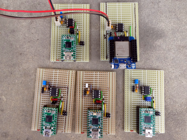
The idea is to create a modbus slave (server) TCP/IP + RTU (TIA485) with an WEMOS D1 mini pro. Naturally we also need a 2 modbus master (client). For TCP/IP we will use a PC or a Raspberry pi with the pymodbus python library. For RTU (TIA485) we use a Teensy with an MAX485.
The modbus client (master)
PC ore Raspberry Pi
A PC (e.g. Raspberry Pi) is the master (called client with TCP).
We will use the pymodbus library by RiptideIO : https://github.com/riptideio/pymodbus.
Documentation can be found here: https://pymodbus.readthedocs.io/en/latest/index.html.
We use a python virtual environment to avoid version and access rights problems. Create the python virtual environment with the following commands and install the pymodbus library:
    mkdir py_env
    python -m venv ~/py_env/env_for_pymodbus
    source ~/py_env/env_for_pymodbus/bin/activate
    pip install pymodbus asyncio pygments click prompt_toolkit --upgrade
You see in your prompt if the environment is activated.
To deactivate use the deactivate command. To later reactivate the virtual environment use again:
    cd ~/py_env/env_for_pymodbus
    source ~/py_env/env_for_pymodbus/bin/activate
Now we can use on the master (client) the Pymodbus Read Evaluate Print Loop (REPL) to access data from a slave (server).
I have an EM24 energy counter from Carlo Gavazzi with modpus tcp. We can start the REPL with:
pymodbus.console tcp --host 192.168.1.76 --port 502
In the console we use the two following commands to read register 0 containing the voltage L1-N and register 0x0B (11) with contains the energy meter identification code:
    > client.read_holding_registers address=0
    > client.read_holding_registers address=11
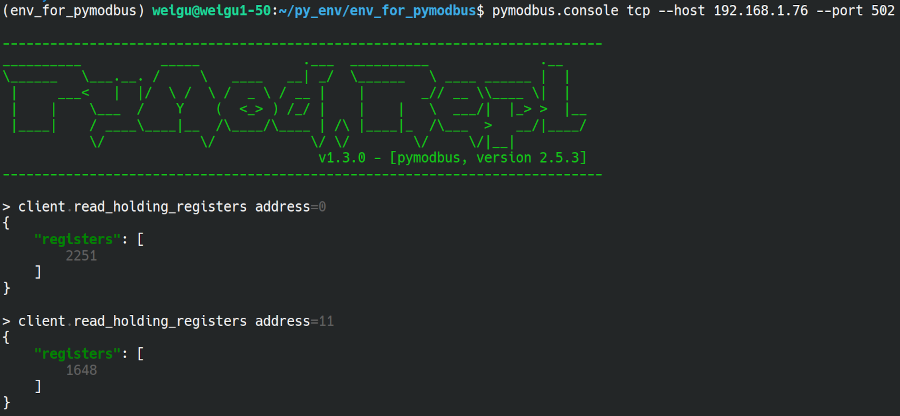
and we get the results:

The voltage is 225.1 V and in the manual of the reader we see that we use item: EM24DINAV23XE1X (=1648).
To read more register in a bunch we can use (no spaces before and after equal sign):
> client.read_holding_registers count=4 address=50000
Teensy 2.0

Circuit
Code
We are using the modbus master library from 4-20mA.
    /*modbus_master_RTU_485_lib_4-20mA
      weigu.lu
      We're using a MAX485-compatible RS485 Transceiver build with a Teensy 2.
      Rx/Tx is hooked up to the pins of the hardware serial port at Serial1.
      PD2 = RXD1 (GPIO 7), PD3 = TXD1 (GPIO 8)
      The data enable and receiver Enable pins connected together and
      are hooked up on Teensy PD7 = GPIO 10
    */

    #include <ModbusMaster.h>               //Library for ModbusMaster (4-20mA)

    const byte MAX485_DE_RE = 10; // halfduplex pin
    const unsigned long MODBUS_BITRATE = 38400;
    const byte MODBUS_SLAVE_ADDRESS = 5;
    const unsigned int HOLD_REG_ADDRESS = 50000;
    const byte NUMBER_OF_REG_2_READ = 4;
    byte result;

    ModbusMaster node;                    //object node for class ModbusMaster

    void preTransmission() {            //Function for setting stste of Pins DE & RE of RS-485
      digitalWrite(MAX485_DE_RE, 1);
    }

    void postTransmission() {
      digitalWrite(MAX485_DE_RE, 0);
    }

    void setup() {
      Serial.begin(115200); // Serial monitor
      while (!Serial);      // Wait for Serial (Teensy Leonardo)
      Serial.println("Serial ok");
      pinMode(MAX485_DE_RE, OUTPUT);
      digitalWrite(MAX485_DE_RE, 0); // receive mode
      Serial1.begin(38400);          // Modbus communication runs at 38400 baud
      node.begin(MODBUS_SLAVE_ADDRESS, Serial1);
      node.preTransmission(preTransmission);  // callback to config transreceiver
      node.postTransmission(postTransmission);// callback to config transreceiver
    }

    void loop() {
      uint16_t data[8];
      // Read NUMBER_OF_REG_2_READ registers starting at HOLDING_REG_ADDRESS)
      result = node.readHoldingRegisters(HOLD_REG_ADDRESS, NUMBER_OF_REG_2_READ);
      if (result == node.ku8MBSuccess)  {
        for (byte j = 0; j < 4; j++)    {
          data[j] = node.getResponseBuffer(j);
          Serial.write(data[j]);
        }
      }
      Serial.println("\n---------------");
      delay(1000);
    }
The modbus server (slave)
Modbus slave (server) TCP/IP + RTU (TIA485) with an WEMOS D1 mini pro.
Connections
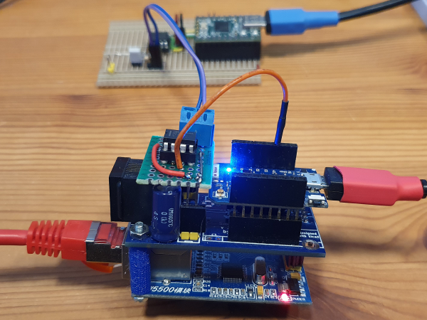
Breakout ethernet board with W5500 connected to WEMOS D1 mini pro. On top a Max485 to get Modbus RTU. In the background a client (master) with a Teensy 2.0.

| WEMOS D1 Mini pro | W5500 | MAX485 |
|---|---|---|
| MISO (GPIO12, D6) | MISO | |
| MOSI (GPIO13, D7) | MOSI | |
| SCK (14, D5) | SCLK | |
| GPIO 0 (D3) | SCS | |
| GPIO 2 (D1 LED) | DE/RE | |
| GPIO 4 (D2 SDA) | TX | |
| GPIO 5 (D1 SCL) | RX |
Do not use GPIO15 (SS, D8), because it is pulled to GND. Programming is not possible; boot fails if pulled HIGH! (Changes on SmartyReader® board V2.1 SS to GPIO0 not GPIO15!)
We use the modbus-esp8266 library by Alexander Emilianov (emelianov): https://github.com/emelianov/modbus-esp8266. Install it with the Arduino Library Manager.
Here is a simple slightly modified sketch from the library examples (File > Examples > modbus-esp8266 > TCP-Ethernet > server) for a server containing 100 holding register with values:
    /* ModbusTCP for W5x00 Ethernet library; Basic Server code example
    * (c)2020 Alexander Emelianov (a.m.emelianov@gmail.com)
    * https://github.com/emelianov/modbus-esp8266
    * This code is licensed under the BSD New License. See LICENSE.txt for more info.
    */

    #include <SPI.h>
    #include <Ethernet.h>       // Ethernet library v2 is required
    #include <ModbusEthernet.h>

    const byte PIN_SS = 0; // GPIO0 for SS Pin
    // Enter a MAC address and IP address for your controller below.
    IPAddress ip(192, 168, 1, 176); // The IP address will be dependent on your local network
    byte mac[] = {
      0xD2, 0xAD, 0xB3, 0xEF, 0xFE, 0x11
    };
    int value = 10;
    ModbusEthernet mb;              // Declare ModbusTCP instance

    void setup() {
      Serial.begin(115200);     // Open serial communications and wait for port to open
      Ethernet.init(PIN_SS);    // SS pin
      Ethernet.begin(mac, ip);  // start the Ethernet connection
      delay(1000);              // give the Ethernet shield a second to initialize
      mb.server();              // Act as Modbus TCP server
      mb.addHreg(0,0,100);      // Add 100 holding register: addHreg(offset, value = 0, numregs = 1)
      for(byte i = 0; i<100; i++) { //write values to hreg
        mb.Hreg(i,value);
        value++;
      }
      Serial.println("Modbus server started");
    }

    void loop() {
      mb.task();                // Server Modbus TCP queries
      delay(50);
    }
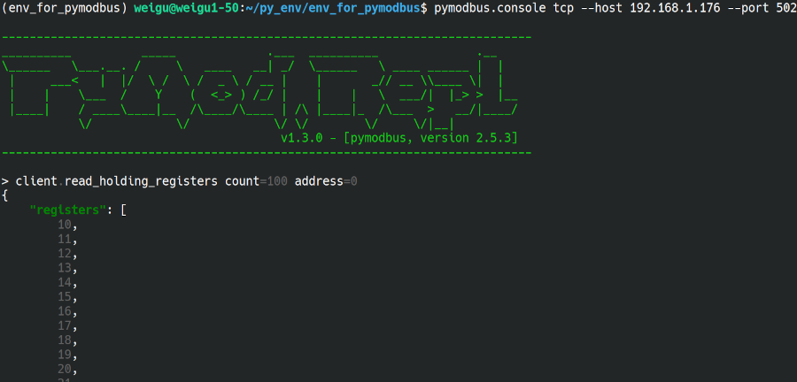
Here is the output in the pymodbus REPL:

More infos about the library commands: https://github.com/emelianov/modbus-esp8266/blob/master/documentation/API.md
Interesting links:
- pymodbus: https://github.com/riptideio/pymodbus
- pymodbus documentation: https://pymodbus.readthedocs.io/en/latest/index.html
- modbus-esp8266: https://github.com/emelianov/modbus-esp8266
- modbus-esp8266 API: https://github.com/emelianov/modbus-esp8266/blob/master/documentation/API.md
