Microcontroller projects
Radiator thermostat hacks
last updated: 25/02/20
Introduction
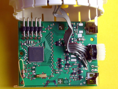
Back in 2010 we used HR20 thermostats from Honeywell (Rondostat) for a school project. They contained an ATmega169 controller from Atmel, and a team from microcontroller.net hacked the thermostat and published the results (in German). Especially their pdf on the hardware revealed many interesting information. The thermostat has a 10 pin header with JTAG for programming, a GPIO Pin (PE2) and a serial interface.
We reprogrammed the thermostat with Bascom (Basic for AVR) and used the serial interface to communicate with the thermostat.
With new techniques like LoRaWan and ESP chips I think re-hacking would be interesting :).
Homeexpert by Honeywell Rondostat style
I have some old thermostats, but thought to look if the thermostat still exists, and for sure I found the same model with a rounder design. It is called homeexpert by Honeywell Rondostat style. To hack something the first challenge is always to open it without damaging the housing. First the big wheel can be removed with a screwdriver and by pulling hard. Than the two pieces of the axes are pulled apart (picture bottom). Now two of the fittings can be pushed with a screwdriver to pull off the display with the buttons.
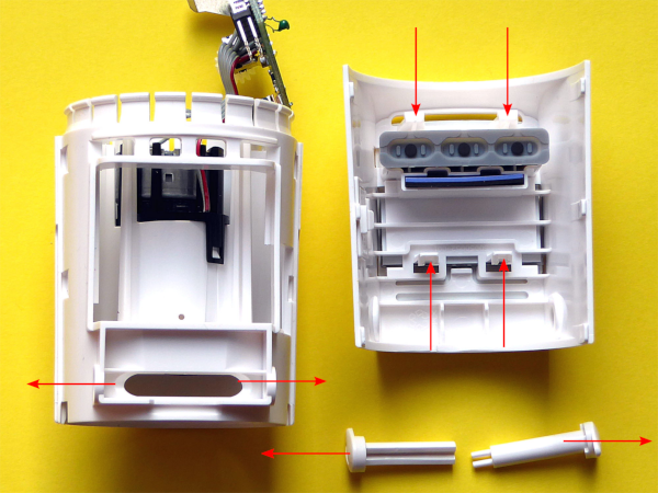
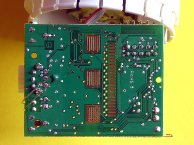
And for sure, the circuit seems to be the same as 9 years ago with an ATmega169 :)).
How to program with Arduino
To program we need a JTAG programmer. I still have my old Dragon board from Atmel (now microchip), that is supported by avrdude, used by Arduino. As the dragon is no more available I also tested with the ATMEL ICE. I purchased the PCB and was disappointed by the tinny header (1.27 mm). So I soldered a normal header to the board.
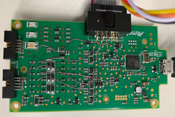
Adapter board
Her is the circuit of a little adapter board to connect the Dragon board to the thermostat.
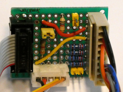
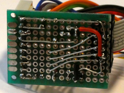
Core and pin layout
Now we need an hardware core to use with Arduino. Fortunately MCUdude did already some work and we can download the core (.zip) at: https://github.com/MCUdude/ButterflyCore.
As I had to make some changes to the core files, I added the changed zipped hardware folder to my downloads. Unzip the folder (called hardware) to your sketchbook. So we get a folder called hardware in the sketchbook folder. In the hardware folder you have a vendor folder with the vendor name (weigu, change at will) and in this folder the architecture folder (here avr).
After copying the harware folder we have to restart Arduino. After this we find the ATmega169 under Butterfly boards.
For the curious I exchanged in line 222 of boards.txt the atmega169p with atmega169and the high_fuses=0xD6 to 0x96. This prevents the bootlader to destroy the JTAG programming access. Then I copied a more recent avrdude.conf to the folder. I added the following lines to programmers.txt, to be able to program with the dragon or the Atmel ICE in JTAG mode:
    dragon.name=Atmel AVR Dragon using JTAG
    dragon.communication=usb
    dragon.program.tool=avrdude
    dragon.protocol=dragon_jtag

    atmel_ice_jtag.name=Atmel-ICE using JTAG
    atmel_ice_jtag.communication=usb
    atmel_ice_jtag.protocol=atmelice
    atmel_ice_jtag.program.protocol=atmelice
    atmel_ice_jtag.program.tool=avrdude
    atmel_ice_jtag.program.extra_params=-Pusb
The file pins_arduino.h in /portable/sketchbook/hardware/weigu/avr/variants/standard/ tells us what numbers Arduino uses for the pins:
AVR pin |
0 |
1 |
2 |
3 |
4 |
5 |
6 |
7 |
|---|---|---|---|---|---|---|---|---|
PA |
44 | 43 | 42 | 41 | 40 | 39 | 38 | 37 |
PB |
8 | 9 | 10 | 11 | 12 | 13 | 14 | 15 |
PC |
28 | 29 | 30 | 31 | 32 | 33 | 34 | 35 |
PD |
18 | 19 | 20 | 21 | 22 | 23 | 24 | 25 |
PE |
0 | 1 | 2 | 3 | 4 | 5 | 6 | 7 |
PF |
45 | 46 | 47 | 48 | 49 | 50 | 51 | 52 |
PG |
26 | 27 | 36 | 16 | 17 | - | - | - |
We get 53 digital pins and 8 analog pins (PF0-PF7 as A0-A7).
Lock and fuse bits
With avrdude we can read the lock and fuse bits:
    cd arduino/arduino-1.8.10/hardware/tools/avr/bin
    ./avrdude -C../etc/avrdude.conf -v -patmega169 -cdragon_jtag -U lock:r:"lock.out":r
    ./avrdude -C../etc/avrdude.conf -v -patmega169 -cdragon_jtag
We must read the file lock.out with an hex editor and see that the lock bits are 0xFC or 0b1111101, so LB1 and LB2 are programmed: Further programming and reading of the Flash and EEPROM are disabled.
And we get: lfuse 0x62, hfuse 0x91 and efuse 0xFD.
lfuse 0x01100010 means:
- Divide clock by 8 internally
- No Clock output on PortE7
- SUT10 = 10 slowly rising power 6CK (14CK + 65ms)
- CKSEL = 0010 internal RC Oscillator at 8MHz
hfuse 0x10010001 means:
- On-Chip debug disabled
- JTAG Interface enabled
- Serial Program and Data Downloading (SPI) enabled
- Watchdog disabled
- preserve EEPROM memory through the Chip Erase cycle
- Boot size 1024
- BOOT Reset Vector disabled
efuse 0x11111101 means:
- Brown-out Detector trigger level at VCC = 1.8V
- Reset disabled
So we choose 1 MHz internal clock and the right brown out level (1.8 V) to program the board.
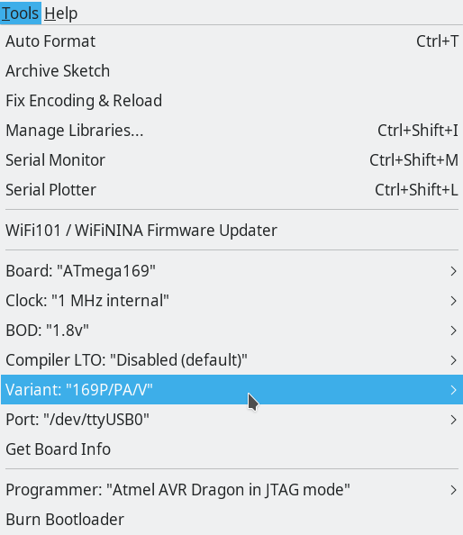
Blink test
Let's test it with a blink sketch for the external GPIO Arduino digital pin 2 (PE2):
    void setup() {
      init_gpio();
    }

    void loop() {
      gpio_low();
      delay(500);
      gpio_high();
      delay(500);
    }

    void init_gpio() {
      pinMode(2, OUTPUT);
    }

    void gpio_low() {
      digitalWrite(2, LOW);
    }

    void gpio_high() {
      digitalWrite(2, HIGH);
    }
Don't forget to press shift to use the external programmer to upload the sketch.
Yes! it works!
To change fuses you can use (e.g. no clock divide by 8), but pay attention to not brick the device (JTAG disabled):
./avrdude -C../etc/avrdude.conf -v -patmega169 -cdragon_jtag -U lfuse:w:0xE2:m
Testing the Hardware
There are many things to test, so it seems a good idea to write a little Arduino library (look at the end of the page). Add the library in your Arduino IDE (Sketch > Include Library > Add .ZIP Library...). The .zip file can be found at the end of page under Downloads. Now we find the examples under
GPIO
As seen we have one GPIO (PE2) on the 10 pin header. Here our blink program using the library:
    /****** hr20_gpio_blink.ino ***************** www.weigu.lu ****************/

    #include <HR20.h>

    HR20 T;                       // create an HR20 object
    /****** SETUP *************************************************************/

    void setup() {
      T.init_gpio_out();          // init GPIO as output
    }
    /****** LOOP **************************************************************/

    void loop() {
      T.gpio_low();               // blink with 200 ms (f=2.5Hz)
      delay(200);
      T.gpio_high();
      delay(200);
    }
Display
The display pins are named Com0-Com2 and Seg0-Seg21. All these pins are connected with the µC pins, set as output.
| Com | 0 | 1 | 2 |
|---|---|---|---|
| 44 | 43 | 42 | |
| PA0 | PA1 | PA2 |
| Seg | 0 | 1 | 2 | 3 | 4 | 5 | 6 | 7 | 8 | 9 | 10 | 11 | 12 |
|---|---|---|---|---|---|---|---|---|---|---|---|---|---|
| 40 | 39 | 38 | 37 | 36 | 28 | 29 | 30 | 31 | 32 | 33 | 34 | 35 | |
| PA4 | PA5 | PA6 | PA7 | PG2 | PC7 | PC6 | PC5 | PC4 | PC3 | PC2 | PC1 | PC0 |
| Seg | 13 | 14 | 15 | 16 | 17 | 18 | 19 | 20 | 21 |
|---|---|---|---|---|---|---|---|---|---|
| 27 | 26 | 25 | 24 | 23 | 22 | 21 | 20 | 19 | |
| PG1 | PG0 | PD7 | PD6 | PD5 | PD4 | PD3 | PD2 | PD1 |
The display uses the 1/3 duty und 1/3 bias mode and also the low power waveform mode. The mode is asynchronous (bit LCDCS = 1) and uses the crystal frequency of 32.768 kHz. This value is divided by (KND) to get frame rate. We choose K=6 (1/3 duty), N=16 and D=6 which gives us a frame rate of 56 Hz
In our lcd_init() function (llok in library) we mask the direction registers (DDR) to set the pins driving the display to output. The 4 LCD register LCDCRA, LCDCRB, LCDFRR, and LCDCCR are set accordingly (see data sheet or pdf from microcontroller.net). Finally the 9 LCDDR (0-2, 5-7, 10-12) register are used to write to the display (look at the same pdf).
Here is a sketch to test the display:
    /****** hr20_test_lcd.ino ******************* www.weigu.lu ****************/

    #include <HR20.h>

    HR20 T;                               // create an HR20 object
    word const DELAY_TIME = 250;          // delay in ms
    char text[] = "-CO2";

    /****** SETUP *************************************************************/

    void setup() {
      T.init_lcd();            // init lcd
      T.lcd_show_text(text);
      delay(DELAY_TIME*12);
    }
    /****** LOOP **************************************************************/

    void loop() {
      for (char i = '0'; i<='9'; i++) {        // numbers from 0-9
        sprintf(text,"%c%c%c%c",i,i,i,i);
        T.lcd_show_text(text);
        delay(DELAY_TIME);
      }
      for (char i = 'A'; i<='Z'; i++) {        // letters from A-Z (small letter if
        sprintf(text,"%c%c%c%c",i,i,i,i);      // capital not possible, space if no
        T.lcd_show_text(text);                 // is possible)
        delay(DELAY_TIME);                     // AbCdEFGHIJ L nOPqrStU   y
      }
      T.lcd_show_text("=-_o");                 // o instead of ° to avoid problems
      delay(DELAY_TIME*4);
      T.lcd_show_text("\"\'[]");
      delay(DELAY_TIME*4);
      for (char i = 'g'; i<='n'; i++) {        // special character accessible with
        sprintf(text,"%c%c%c%c",i,i,i,i);      // small letters from g-n
        T.lcd_show_text(text);                 // g=,h-,i_,j°,k",l’,m[,n]
        delay(DELAY_TIME);
      }
      for (char j = 0; j<5; j++) {            // turn 10 times
        for (char i = 'c'; i<='f'; i++) {      // c n invc u turning effect for wait
          sprintf(text,"%c%c%c%c",i,i,i,i);
          T.lcd_show_text(text);
          delay(DELAY_TIME/2);
        }
      }
      T.lcd_clear();
      delay(DELAY_TIME);
      for (byte k = 0; k<=33; k++) {      // c n invc u turning effect for wait
        Serial.print(k);
        T.lcd_show_special(k);
        delay(DELAY_TIME);
        T.lcd_clear_special(k);
        delay(DELAY_TIME);
      }
    }
Motor
Now lets turn the motors. They need the following Arduino pins: 12 (PB4), 15 (PB7), 16 (PG3) and 17 PG4:
| 12 (PB4) | 15 (PB7) | 16 (PG3) | 17 (PG4) | |
|---|---|---|---|---|
| STOP | 0 | 0 | 0 | 0 |
| Open valve | 1 (PWM) | 0 | 1 | 0 |
| Close valve | 0 (PWM) | 1 | 0 | 1 |
In the original firmware pin PB4 (OC0A) is used to generate a PWM signal with a frequency of 15.625 kHz (?) to regulate the power supplied to the motor. When the valve is opened, PB4 uses a duty cycle of about 70%. For closing the duty cycle is about 30%. As Timer0 is used by Arduino for delay, we don't mess up with the frequency and let the PWM frequency at 64 Hz.
We will use the same PWM and duty cycles. If needed they can be changed in the library.
    /****** hr20_test_motor.ino ***************** www.weigu.lu ****************/

    #include <HR20.h>

    HR20 T;                    // create an HR20 object
    /****** SETUP *************************************************************/

    void setup() {
      T.init_motor();          // init motor
    }
    /****** LOOP **************************************************************/

    void loop() {
      T.motor_open_valve();    // open valve for 3s
      delay(3000);
      T.motor_close_valve();   // close valve for 3s
      delay(3000);
      T.motor_stop();          // stop motor for 10s
      delay(10000);
    }
Reflex light barrier
The motor has a reflex light barrier to check if it is turning. The sensor can be powered on and off with pin 3 (PE3). Pin 4 (PE4) is the input of the light barrier. We activate the reflex light barrier only if the motor turns. An interrupt in the library handles a reflex light barrier counter. It is always set to 0 before the motor begins to turn. For closing the valve we get negative values. There is a function to display the counter on the LCD screen. if needed the method motor_stop() can return the counter (look at HR20.h in the library).
    /****** hr20_test_reflex_light_barrier  ******* www.weigu.lu **************/

    #include <HR20.h>

    HR20 T;                    // create an HR20 object

    long millis_now, millis_prev;
    long open_time = 3000, close_time = 3000, stop_time = 3000;
    char text[5] = "-CO2";

    /****** SETUP *************************************************************/

    void setup() {
      T.init_motor();          // init motor
      T.init_reflex();         // init reflex light barrier
      T.init_lcd();            // init lcd
      T.lcd_show_text(text);
      delay(2000);
      millis_prev = millis();
    }
    /****** LOOP **************************************************************/

    void loop() {
      millis_now = millis();
      if ((millis_now - millis_prev <= open_time) &&
         (T.get_motor_direction() != 1)) {
        T.motor_open_valve();    // open valve for 3s
      }
      else if ((millis_now - millis_prev > open_time) &&
               (millis_now - millis_prev < (open_time + close_time)) &&
               (T.get_motor_direction() != 0)) {
        T.motor_close_valve();   // close valve
        delay(1000); // to read the result
      }
      else if ((millis_now - millis_prev > (open_time + close_time)) &&
               (millis_now - millis_prev < (open_time + close_time + stop_time)) &&
               (T.get_motor_direction() != 255)) {
        T.motor_stop();   // close valve
      } else if (millis_now - millis_prev > (open_time + close_time + stop_time)) {
        millis_prev = millis();
      }
      T.lcd_show_reflex_counter(T.get_reflex_counter());
    }
Switch "thermostat mounted"
The switch "thermostat mounted" 8 (PBO) is closed if the thermostat is not mounted! We use an internal pull up resistor.
    /****** hr20_test_switch_thermostat_mounted.ino **** www.weigu.lu ********/

    #include <HR20.h>

    HR20 T;                    // create an HR20 object
    /****** SETUP *************************************************************/

    void setup() {
      T.init_switch_tm();      // init switch "thermostat mounted"
      T.init_lcd();            // init lcd
    }
    /****** LOOP **************************************************************/

    void loop() {
      if (T.read_switch_tm()) {
        T.lcd_show_text("0000"); // OPEN thermostat mounted
      }
      else {
        T.lcd_show_text("1111"); // CLOSED thermostat not mounted
      }
    }
Temperature with Thermistor
A 27k resistor in series with a A temperature sensor (NTC Thermistor) is alimented with VCC over pin 48 (PF3, output). The NTC is connected to the internal ADC on pin 47 (PF2). The non linearity of the NTC is handled by the library as described in the pdf from microcontroller.net. As the reference voltage of the ADC is VCC, a drop of the battery voltage does not affect the result.
Here is a sketch to measure the temperature and the battery voltage:
    /****** hr20_test_temperature_and_voltage.ino ********* www.weigu.lu ******/

    #include <HR20.h>

    HR20 T;                               // create an HR20 object
    word const DELAY_TIME = 1500;         // delay in ms
    char text[] = "-CO2";

    /****** SETUP *************************************************************/

    void setup() {
      T.init_lcd();            // init lcd
      T.init_ntc();            // init NTC
      T.lcd_show_text(text);
      delay(DELAY_TIME);
    }
    /****** LOOP **************************************************************/

    void loop() {
      T.lcd_show_temperature(T.get_temperature());
      delay(DELAY_TIME);
      T.lcd_show_voltage(T.get_voltage());
      delay(DELAY_TIME);
    }
User commands
We get three push-buttons and 2 inputs from the rotary pulse encoder. The 3 push-buttons are: AUTO/MANU on 11 (PB3), °C on 10 (PB2) and PROG on 9 (PB1). The rotary pins are: A on 13 (PB5) and B on 14 (PB6). They all use pull-up resistors, so we get negative logic. The rotary method returns a 1 for clockwise rotation, a 0 for no rotation, and a -1for counterclockwise rotation.
Momentarily we use polling for the user commands.
    /****** hr20_test_buttons_and_rotary.ino ************* www.weigu.lu ******/

    #include <HR20.h>

    HR20 T;                               // create an HR20 object
    word const DELAY_TIME = 1500;         // delay in ms
    char text[] = "-CO2";
    byte buttons, count = 8;
    char rotary;  // can get negative

    /****** SETUP *************************************************************/

    void setup() {
      T.init_lcd();            // init lcd
      T.init_push_buttons();
      T.init_rotary();
      T.lcd_show_text(text);
      delay(DELAY_TIME);
      T.lcd_clear();
      T.lcd_show_special(count);
    }
    /****** LOOP **************************************************************/

    void loop() {
      for (byte i = 0; i<4; i++) {
        text[i] = ' ';
      }
      buttons = T.get_push_buttons();
      if ((buttons & 0x01) == 0) {
        text[3] = 'P';
      }
      if ((buttons & 0x02) == 0) {
        text[2] = 'C';
      }
      if ((buttons & 0x04) == 0) {
        text[1] = 'U';
        text[0] = 'A';
      }
      T.lcd_show_text(text);
      rotary = T.get_rotary();
      if (rotary == 1) {  // forward
        if (count == 31) count = 30;
        count++;
        T.lcd_show_special(count);
      }
      if (rotary == -1) { // backward
        T.lcd_clear_special(count);
        if (count <= 8) count = 8;
        count--;
      }
    }
Downloads
