Microcontroller projects
LoRa sender with Promini LoRa board running on batteries
last updated: 2020-10-04
Introduction
I want an Arduino mega328p driven temperature and humidity sensor, sending data over LoRa and running forever :) on 2 AAA alkaline batteries.
A first step was to dive deep into sleep modes: http://weigu.lu/microcontroller/tips_tricks/lp_sleep_tips_tricks/index.html.
Then I tested a circuit on a breadboard: http://weigu.lu/microcontroller/lora_p2p_SX_lp_bb/index.html.
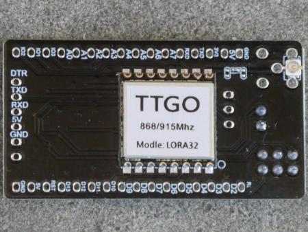
The next step was to use a PCB and I found the TTGO promini lora board from LILYGO which was really cheap and contained an Arduino (mega328p) and the SX1276 chip.
Promini LoRa board
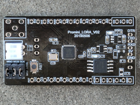
I use the 868 MHz version (Europe) and the board came in version 2. Pictures showed the older version, and there was no circuit available. To understand the board, I had to draw the circuit.
Circuit
Burning the bootloader and testing the program
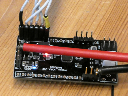
A next step to lower the current is to burn a bootloader running on 8 MHz internally instead of the typical external 16 MHz crystal. I use the miniCore bootloader as described here. To burn the bootloader I use an AVRISP mk2, but it can also be done with an Arduino working as bootloader. In either way you have to solder an adapter cable to fit the 6 pins on the promini board (MOSI, MISO, SCK, RST, 5V, GND). The board has to be powered with 5 V and it is important to remove the three jumper connecting SPI to the LoRa chip (picture on the right).
After burning the bootloader, we can program the chip as usual with the Arduino IDE (8 MHz internal, BOD 1.8 V), powered with 3 V. Don't forget to reconnect the jumper (picture on the left).
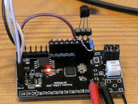
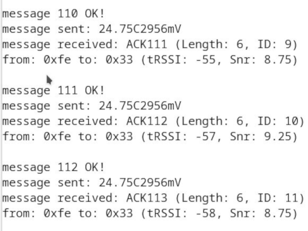
The temperature sensor (DS18B20) is connected as described in the sleep chapter and when we run the software from this chapter we get the output of the serial monitor shown in the next picture (gateway also running).
Everything is fine (alles in Butter), but...
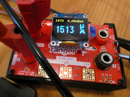
When connecting the current ranger we see that the current when not sending is 1.5 mA!!, 150 times higher than with our stripped Arduino.
Pimping the board
So we will change this. From the schematic it is clear that the components not needed draw a current. As an example, the two 100 kΩ resistors (R7 and R8) that could be used to measure the battery voltage need 3 V/200 kΩ = 15 µA. So we will eliminate them and the ICs not needed using e.g. a hot-air soldering station.
Don't eliminate capacitors especially C5 (red circle), is needed to program the board.
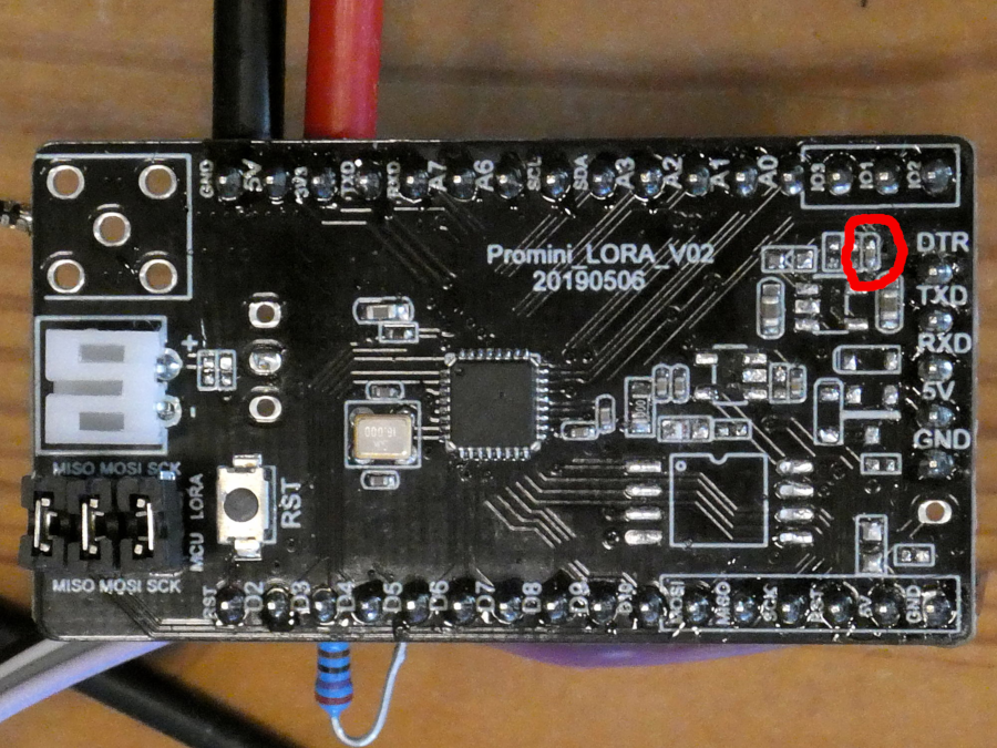
To run the board by connecting a battery on J7 we need a connection from this connector to 3 V. I soldered a bridge from J7 to pin 2 of J8 (purple line in schematic).
Changing the sensors
I want to add the humidity, so the DS18B20 has to be replaced by a combined sensor.
