Microcontroller projects
Efficient alarm clock with low electromagnetic radiation,
big display and music player
last updated: 21/01/18
Short description
Yes I'm getting older! So I needed an alarm clock with bright LEDs to be seen in the night without glasses. After reading an article from Julien Thomas about an energy efficient alarm clock in the German ham-magazine Funkamateur in 2008 I decided to build my own version of this clock. I found especially interest in the idea of using a capacitive power supply to reduce electric smog (reduced magnetic field). Changes to Julien's concept were an ATmega8 (instead of ATiny2313), a real time clock (RTC DS1307) with gold-cap and a DCF77 receiver witch is synchronizing the clock at 4am. The software was written in assembler. For more details about the old version look at the end of this page My old alarm clock worked without flaws until today (and still does its job), but the sound of the buzzer wasn't very attractive. So I decided to rebuild the clock with newer components. The new clock has the following features:
Features
- capacitive power supply to reduce electric smog
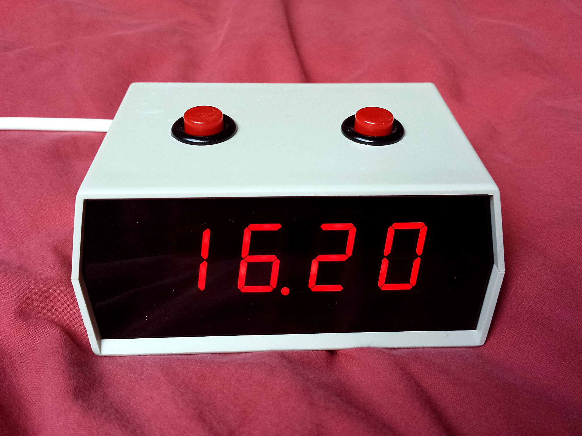
- big and efficient 1.2" 4-digit 7-segment display (I2C)
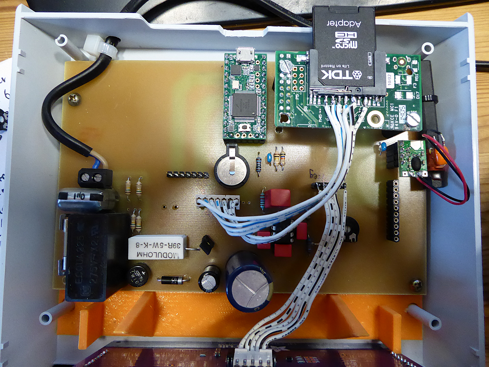
- Teensy 3.1 board with 12 Bit DAC (SD-card wav player) and internal Real Time Clock (RTC)
- efficient I2C class D amplifier (89% efficient with 8Ω speaker at 1.5 Watt)
- DCF77 receiver
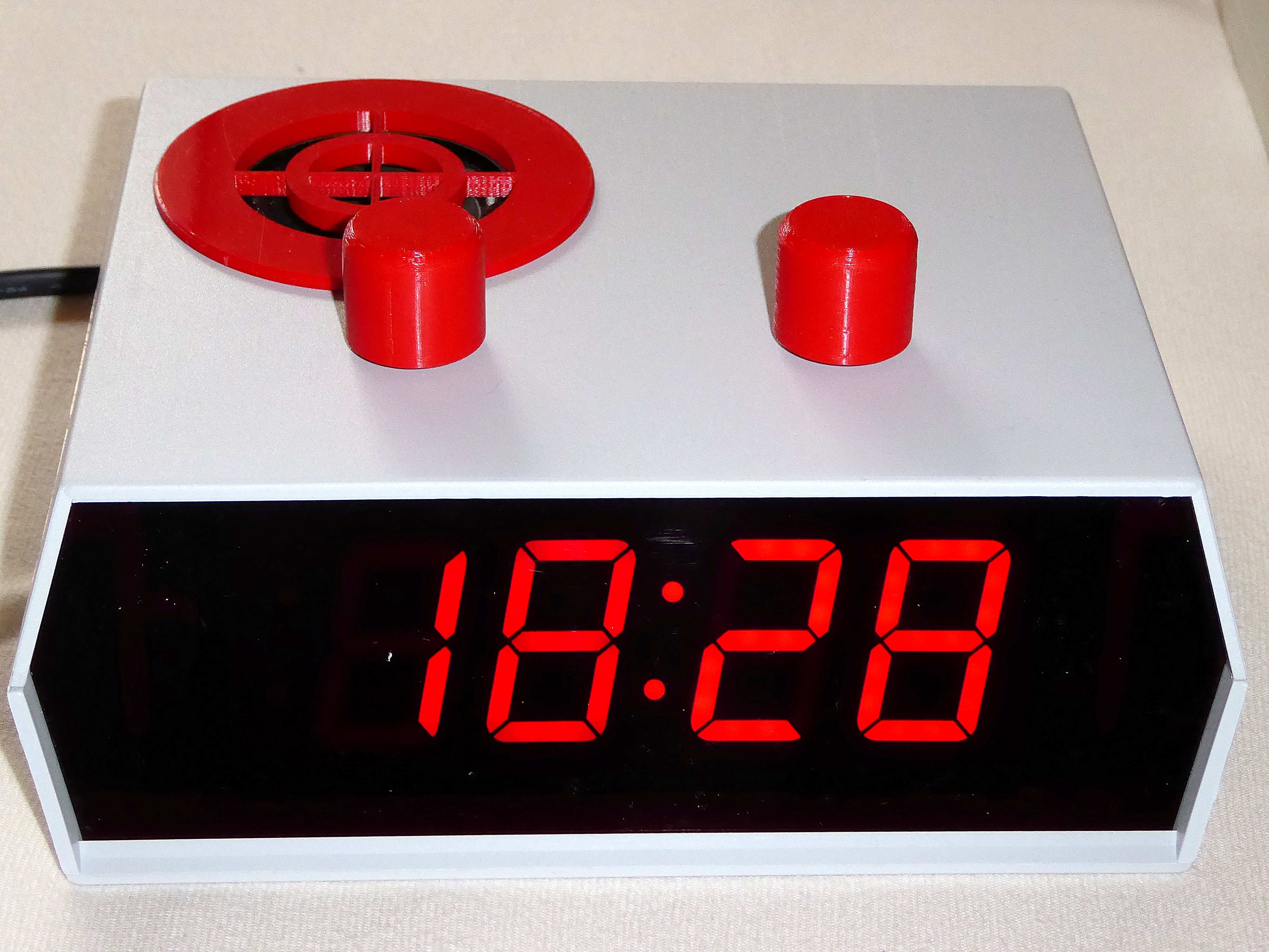
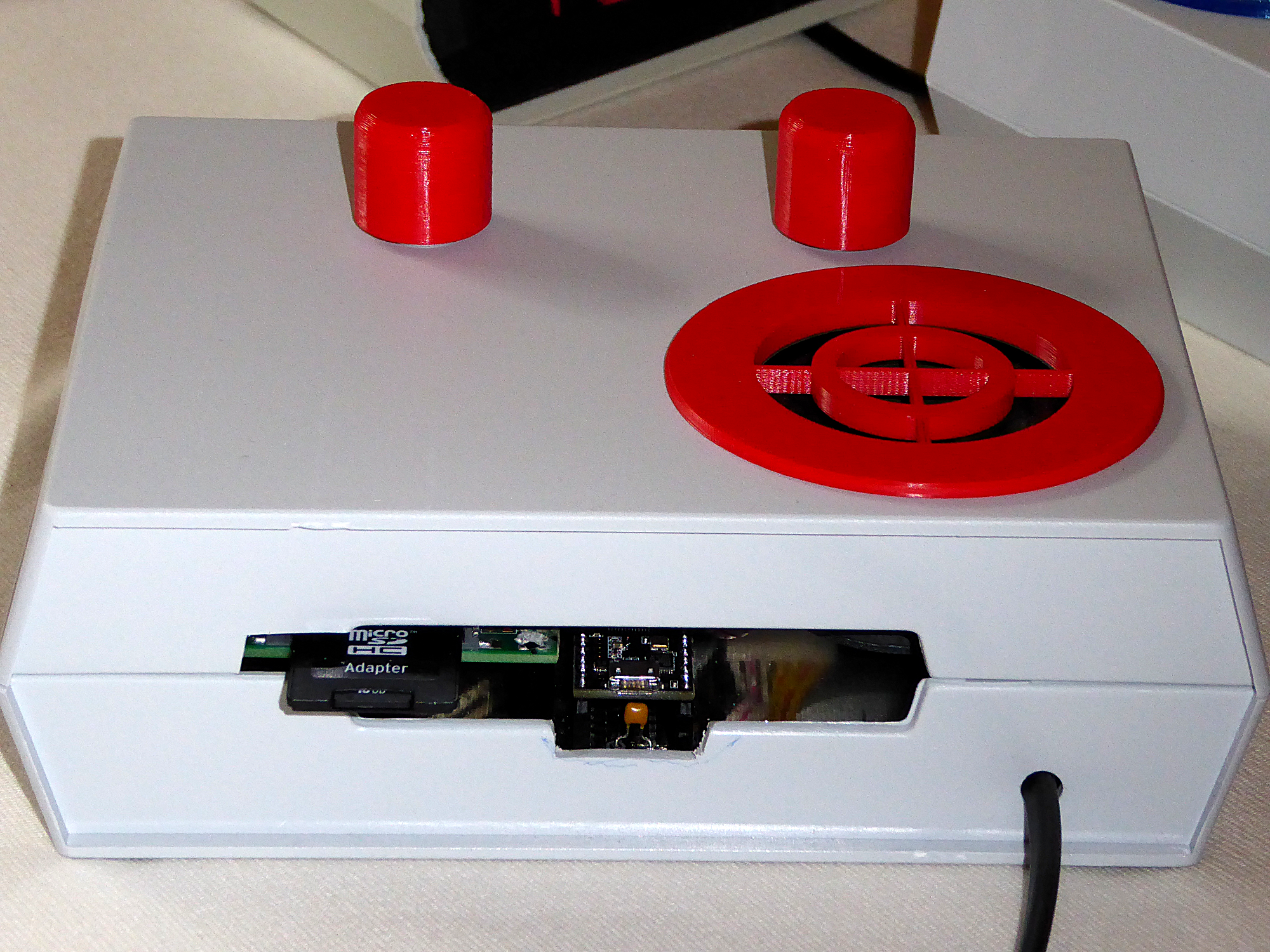
- two rotary Encoder with switch for easy and intuitive control
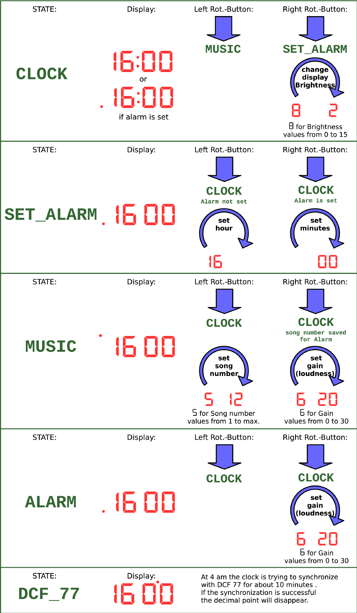
- state machine programmed with Arduino (teensyduino) for easy enhancements in the software
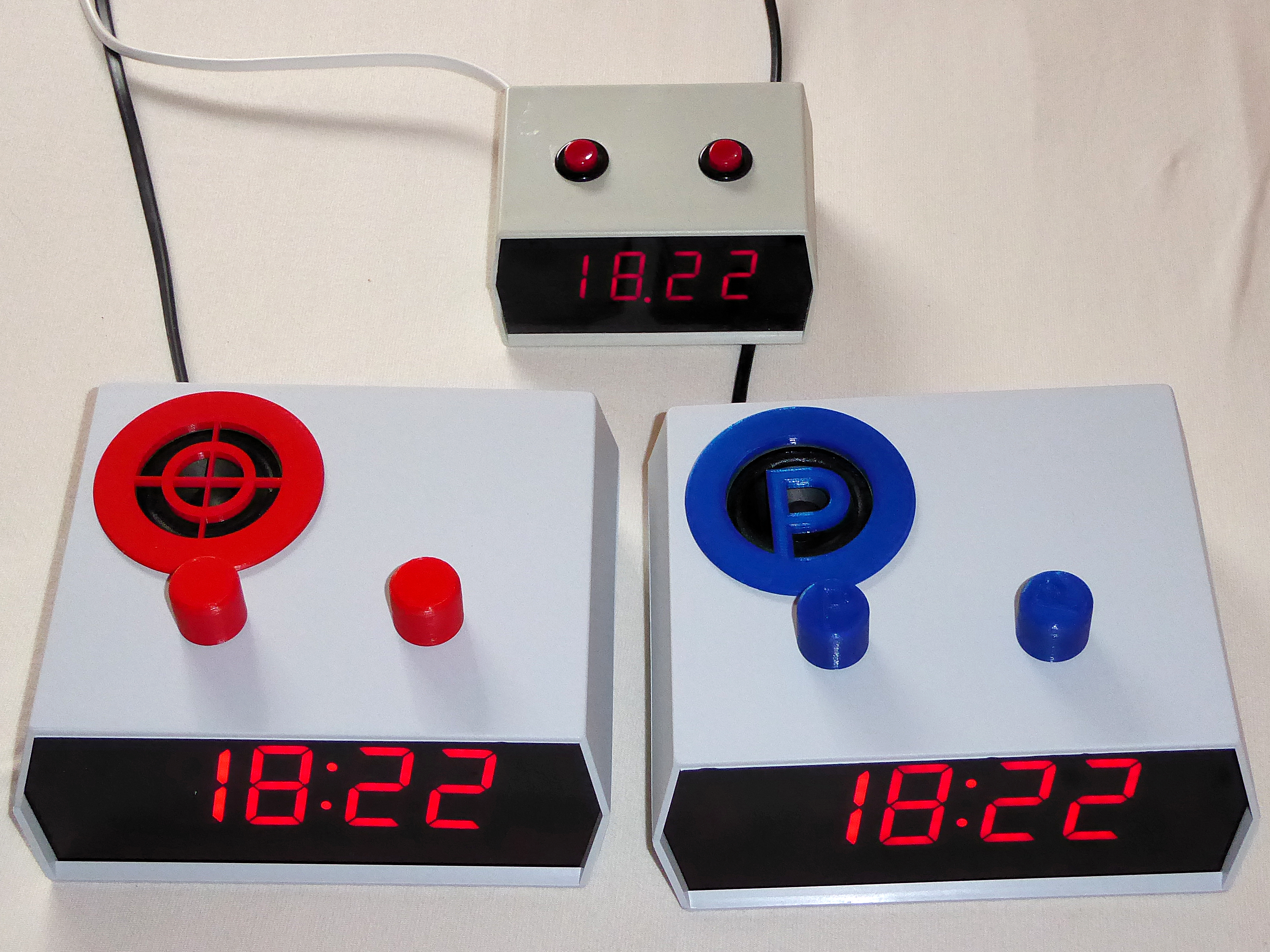
Images
Instruction sheet
Building the clock
Caution!!!
THE CIRCUIT PRESENTED HERE IS AT AC MAINS POTENTIAL, AND THEREFORE EXTEMELY DANGEROUS TO TOUCH IN SWITCHED ON POSITION. UTMOST CARE AND CAUTION IS ADVISED. NEWBIES PLEASE KEEP AWAY.
USE AN ISOLATION TRANSFORMER FOR TESTING !! DO NOT TOUCH THE PCB. The circuit has to be housed in a case that will not allow to touch any metallic parts (appliance class II). Its advised to use an electrical insulating spray for the PCB. NEVER USE THE USB CONNECTOR WHEN THE CLOCK IS POWERD BY THE CORD.
If you build this alarm clock, it is on your own risk. I accept no responsibility for any damage that may result in building this clock.
BOM
First you need to get all the components. I ordered the Teensy and the Adafruit components directly in the US, but it is also possible to get them in Europe from different shops (ex.: http://www.watterott.com).
- Teensy 3.1 board
- 1.2" 4-digit 7-segment display (I2C) from Adafruit
- I2C class D amplifier TPA2016 from Adafruit
- DCF77 receiver from pollin.de](https://www.pollin.de/p/dcf-empfangsmodul-dcf1-810054)
- 2 rotary Encoder with switch from Bourns (PEC16-42AAF-S0024, mouser.com)
- 1 rectifier B500C1500RUND (reichelt.de)
- 1 Zener diode 5.1V 5W (ZD-5W 5,1V, reichelt.de)
- 1 cap X2 2.2µ (PAN-X2-2200N, reichelt.de)
- 1 cap X2 100n (MP3-X2 100N, reichelt.de)
- 1 housing TEKO D14 (TEKO D14, reichelt.de)
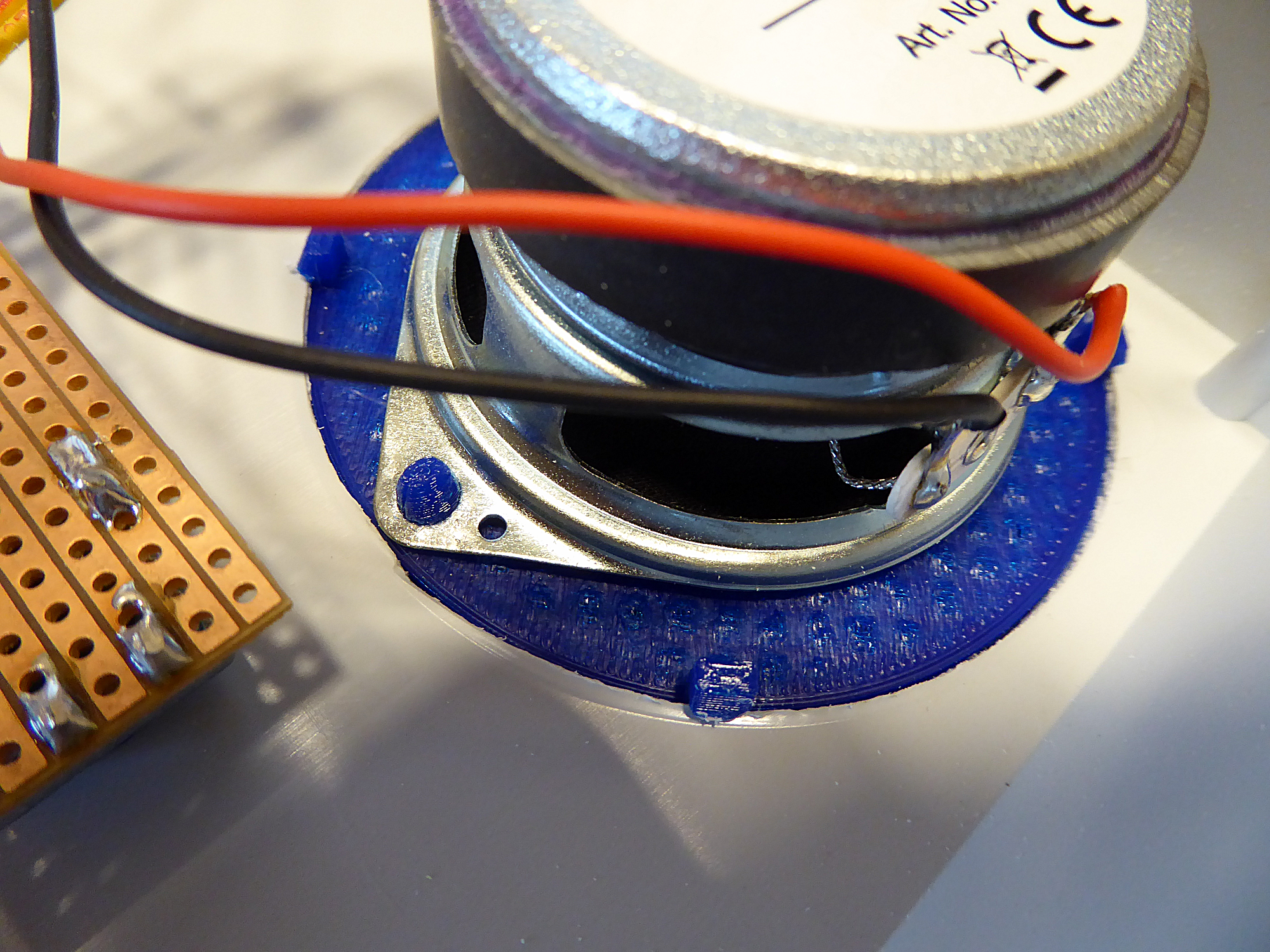
- 1 speaker Visaton 8 Ohm 5cm (VIS FRS 5-8, reichelt.de)
- 1 battery holder keystone (534-500, mouser.com)
- 1 lithium battery 3V CR1225
- 6 caps 100n
- 1 cap 6800µF 10V
- 1 cap 10n
- 1 cap 1n
- 2 caps 470pF
- 1 SD Card holder (see text)
- 1 fuse holder
- 1 fuse 500mA
- 1 fixed terminal block (571-2828362, mouser.com)
- 1 resistor 47Ω 5W
- 4 resistors 150k 1/4W
- 1 resistor 1/4W: 1k, 12k, 5.6k, 27k, 68k (opt:100k, 56k)
- 1 potentiometer 10k lin
- 1 opamp MCP6002
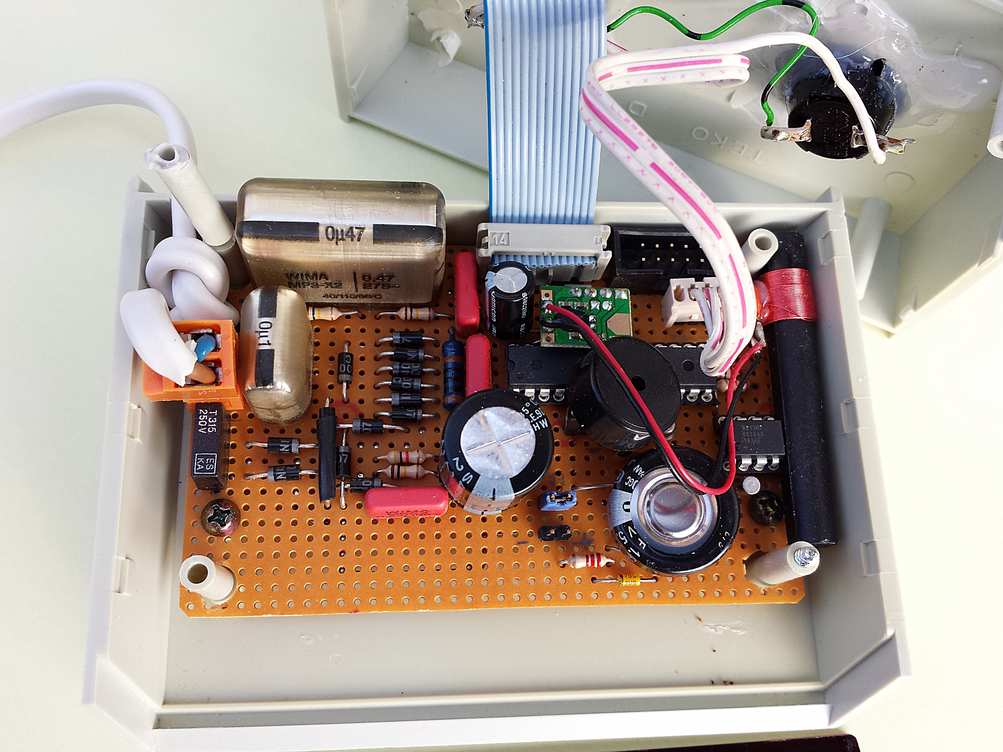
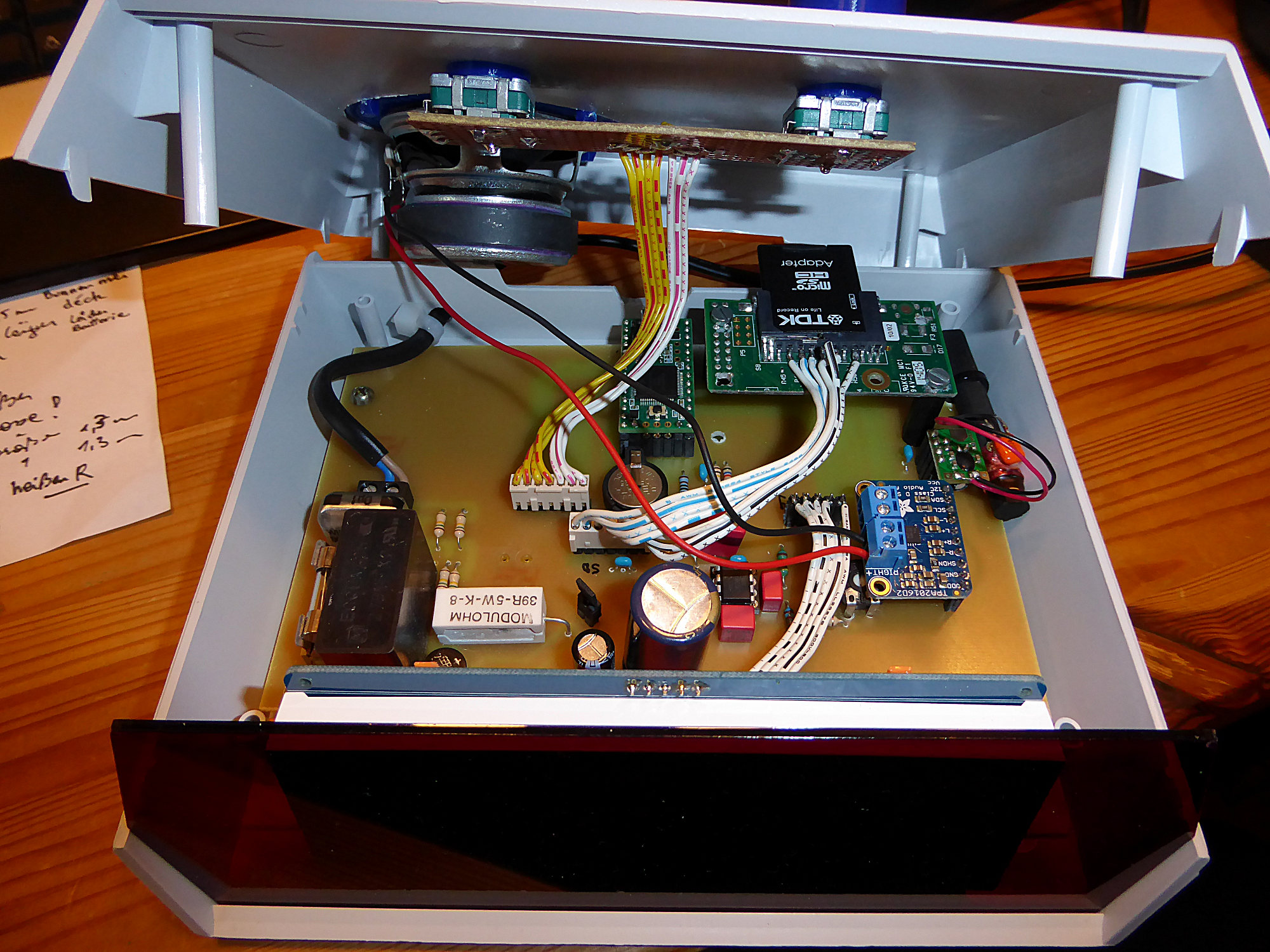
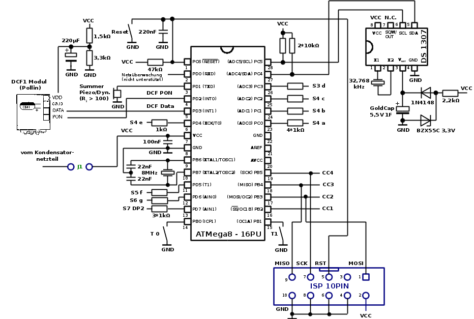
Circuit
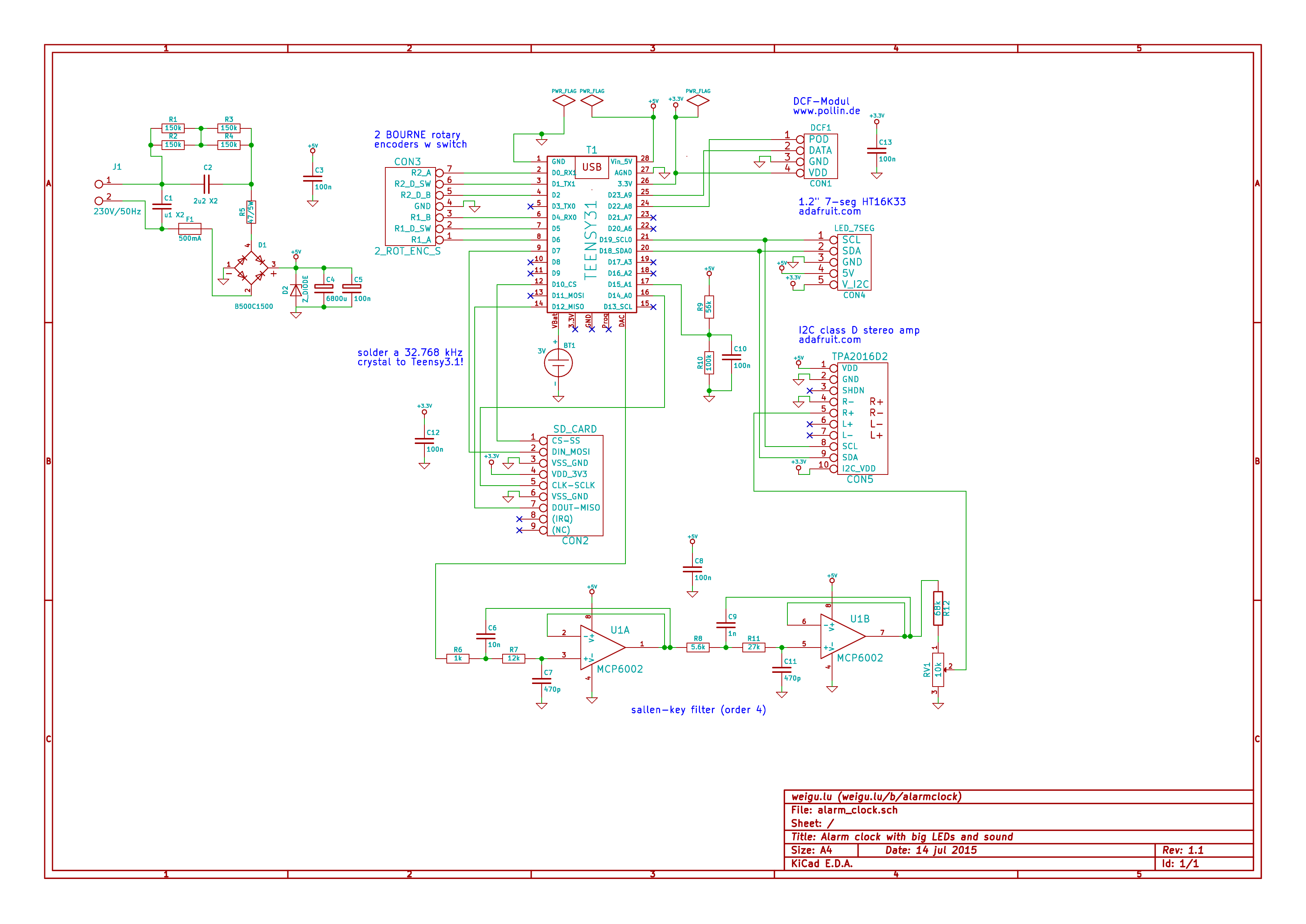
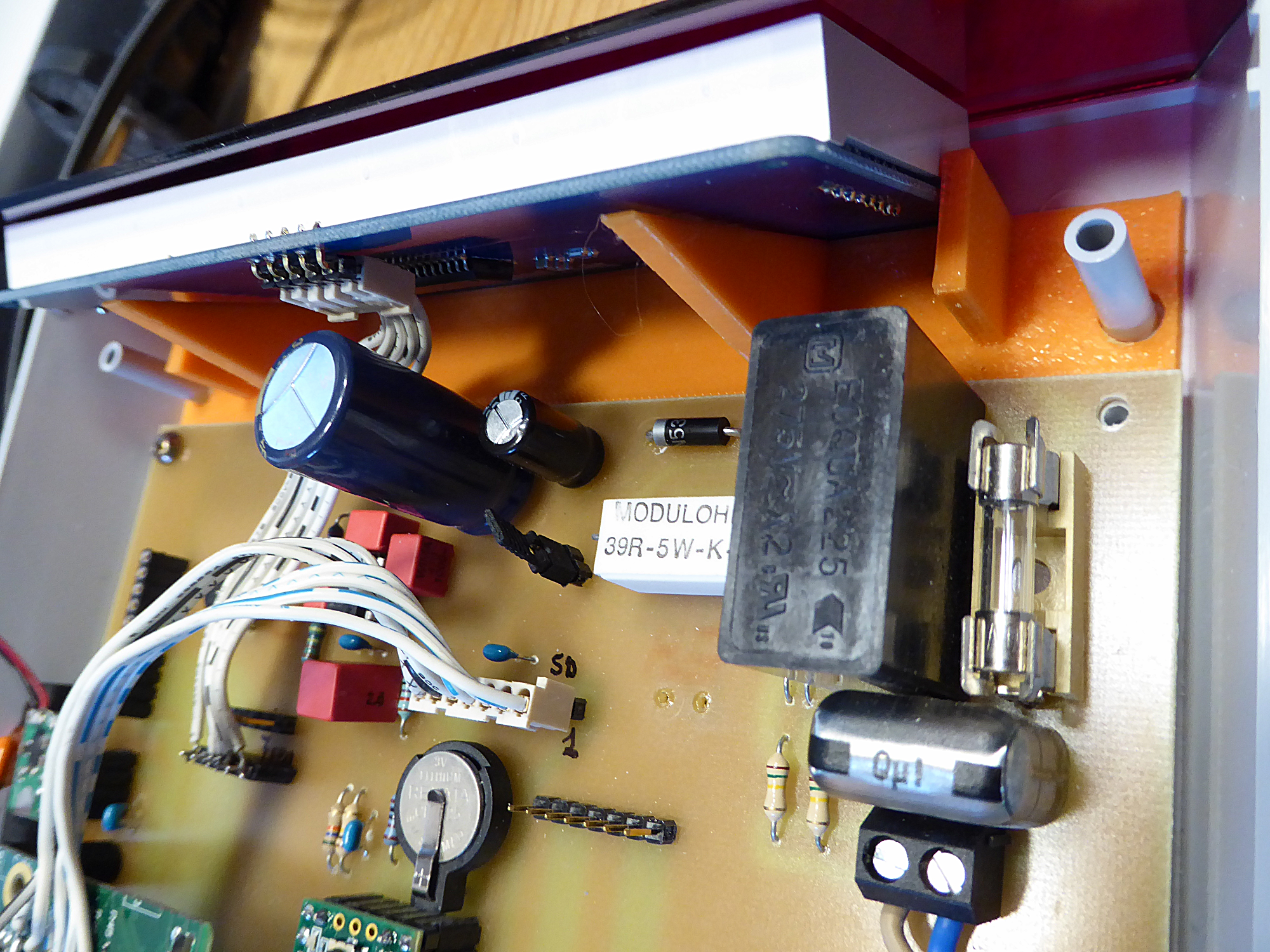
The capacitive power supply is mainly the 2.2µF (XC = 1/2πfC = 1447Ω) cap connected in series with the 47Ω resistor, two diodes (0.7V) and the zener diode (5.1V). This gives 230V-2*0.7V-5.1V = 223.5V on Z=1448Ω (R is not relevant) and a current of I = U/Z = 154mA. The heat on R is 47Ω*0.154^2 = 1.1W and so the loss of our clock is under 2W (17,5kWh/a).The clock needs about 100mA when playing music.
It is important to use X2 caps! because ordinary capacitors will be destroyed by the rushing current from the mains. X2 caps are suitable for connection directly to the mains (film caps)
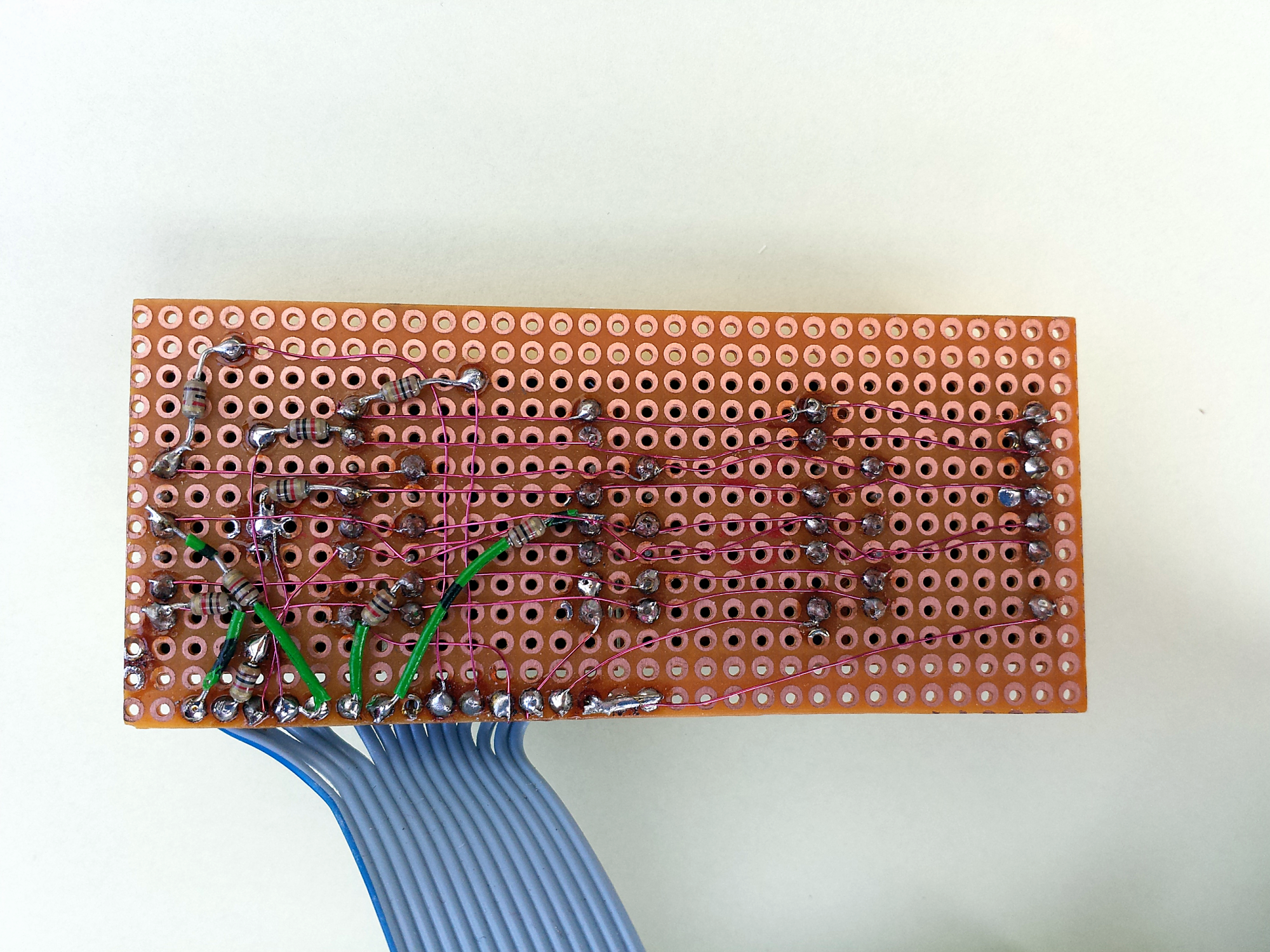
####PCB and 3D-prints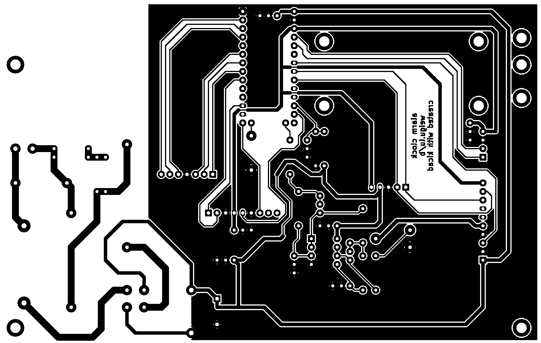
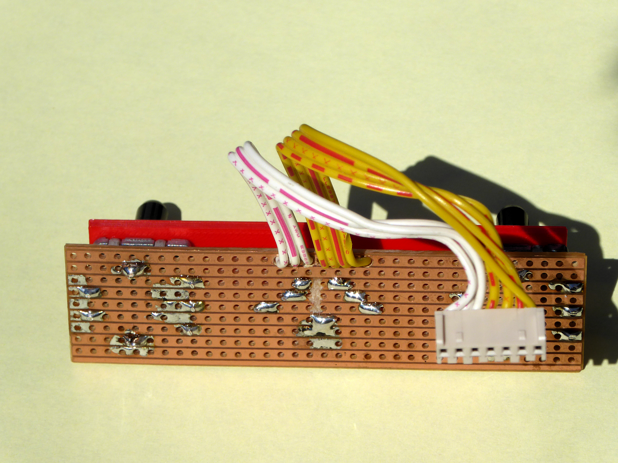
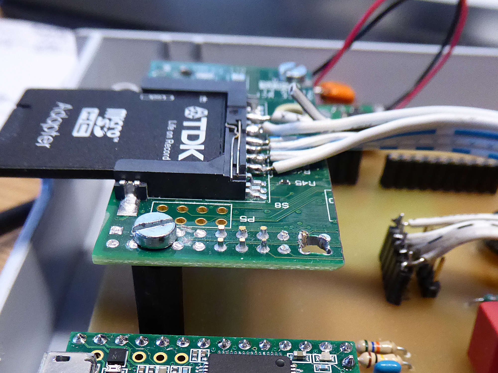
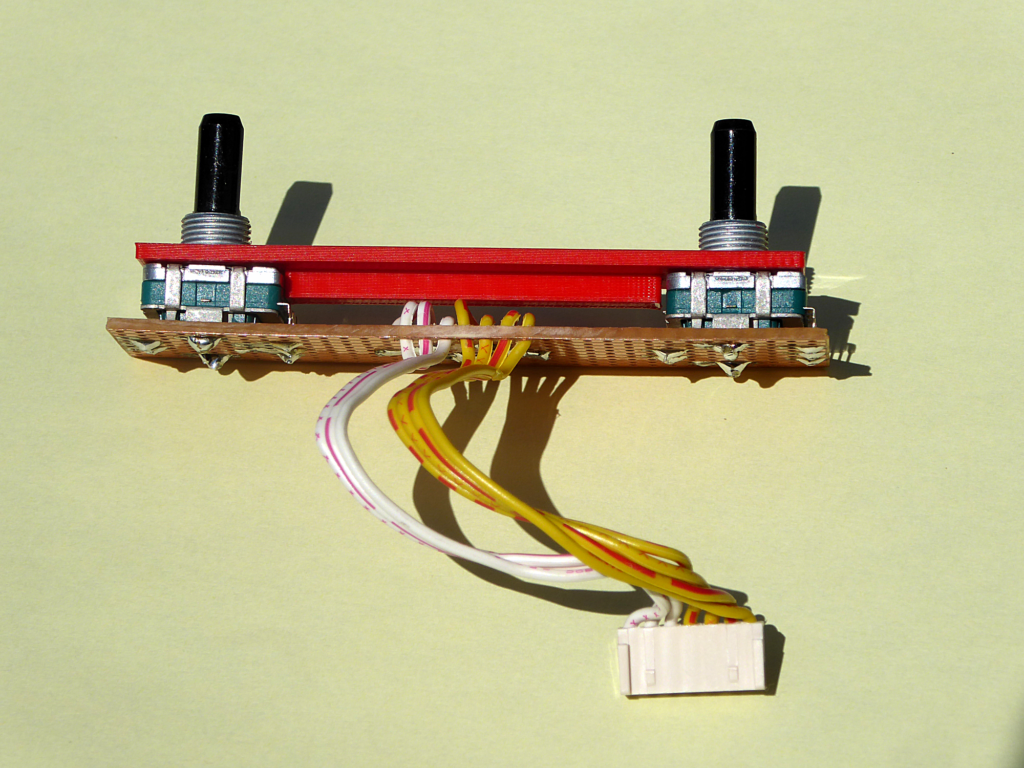
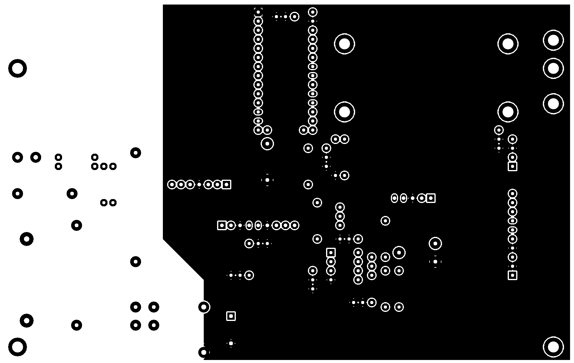 The PCB was designed with kicad an open source software. The simplest way is to etch a single sided board (100*160mm) by using the following postscript file for the exposition to light. The rotary encoders where fixed on a piece of standard breadboard. A bricked raspberry was recycled to hold the SD-Card. Alternatively an SD-card breakout-board can be used or a piece of breadboard with a soldered SD-Card-holder.
- alarm_clock-B_Cu.ps
- all kicad files (zip)
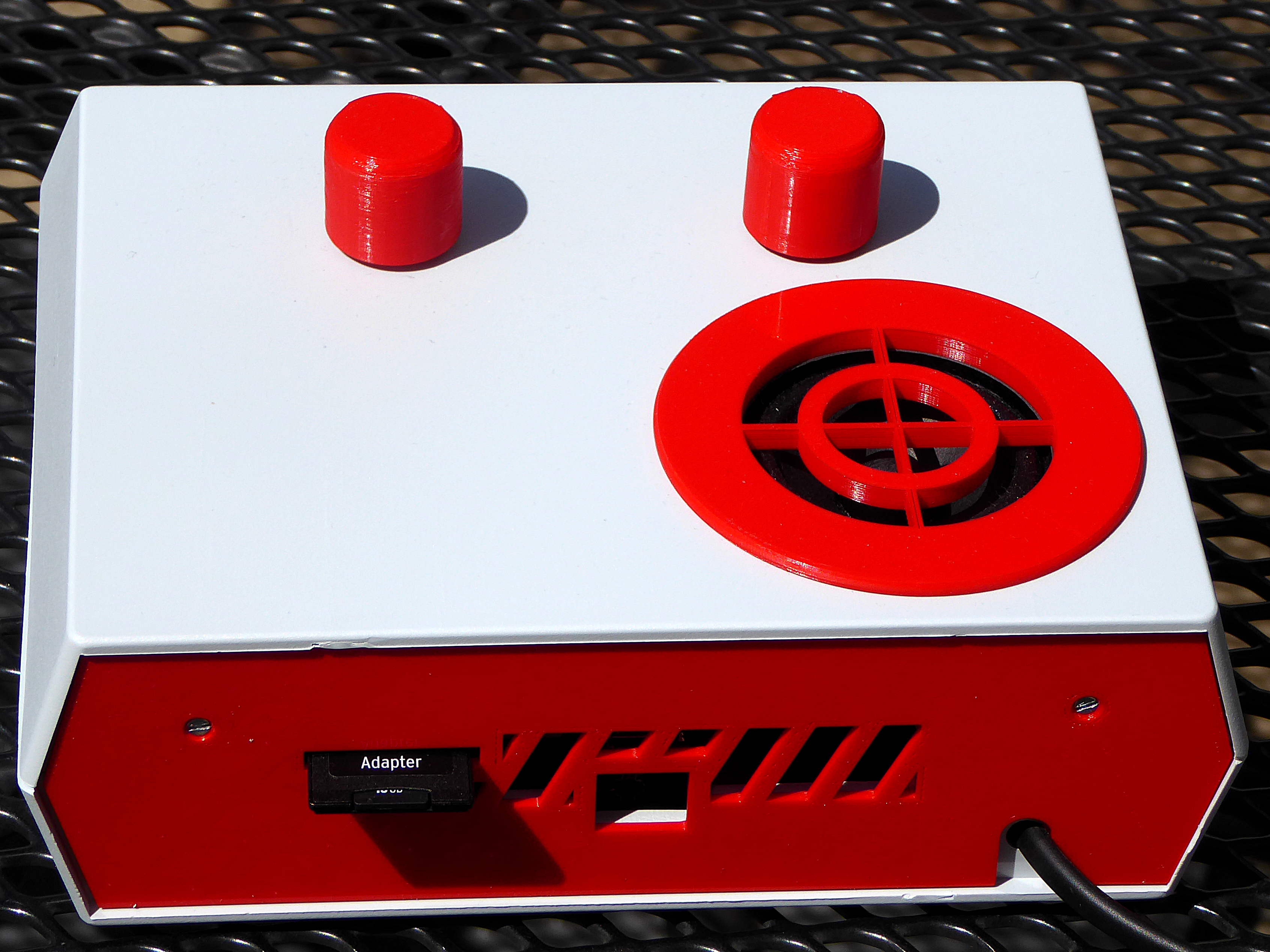
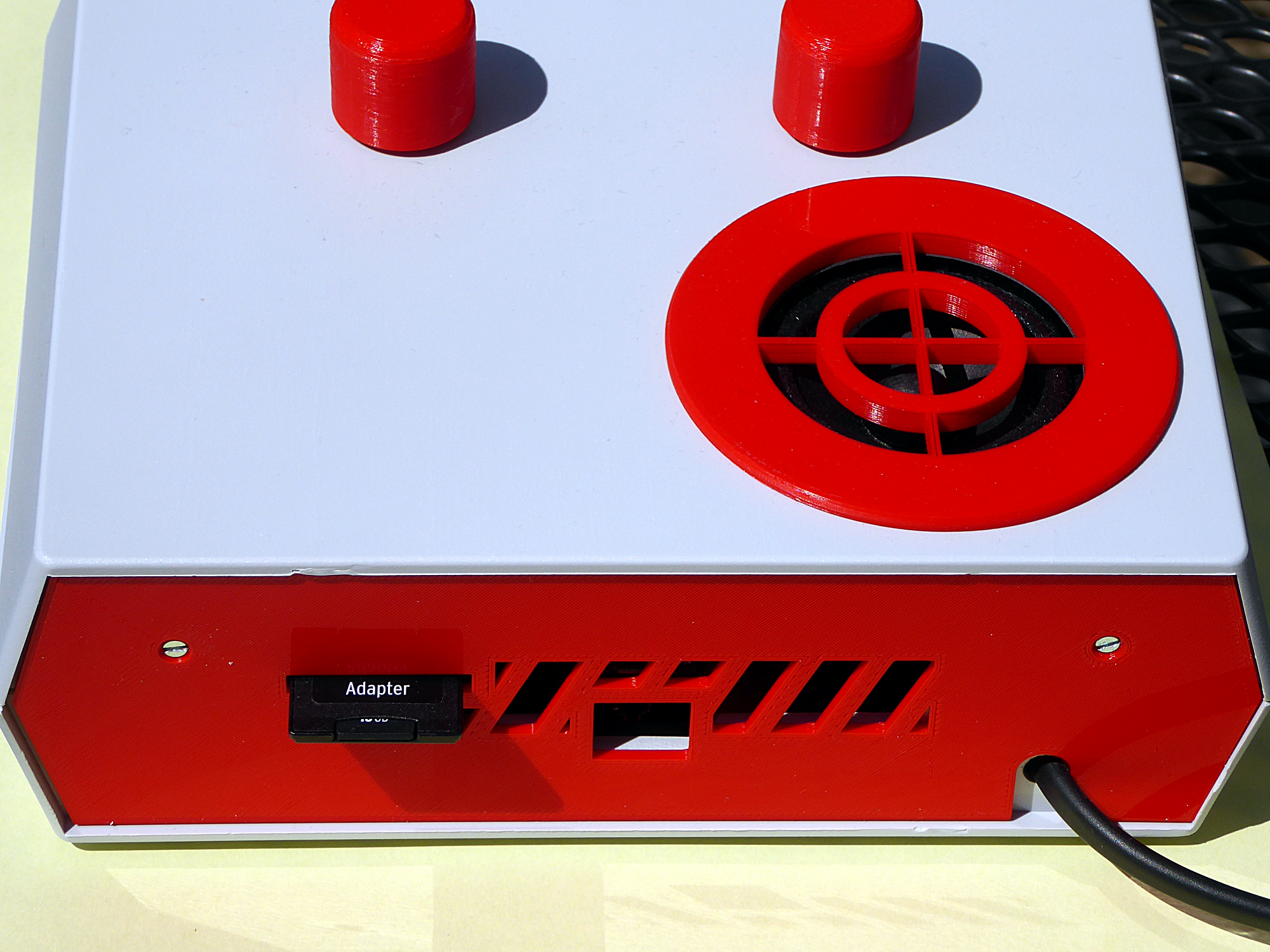
To fix the speaker I used a 3D-printed part (PLA). It will fit in an 69mm hole, that was drilled with an 68mm keyhole saw. Another piece is hiding the metallic parts on the back. If you have little children it would be wise to cover the USB-hole. The aeration slits are needed because of the heat generated by the 5W resistor. A 3d-printed stand is used for the LED-backpack. A distance holder and caps for the rotary encoders are other 3d-printed parts.
- alarm_clock_speaker_holder.stl
- alarm_clock_washer.stl
- alarm_clock_button.stl
- alarm_clock_LED_holder.stl
- alarm_clock_rear_cover.stl
Files on thingiverse.com
####Software
The software was written with Arduino (1.6.4) and Teensyduino. Some libraries are included in the folder
The PCB was designed with kicad an open source software. The simplest way is to etch a single sided board (100*160mm) by using the following postscript file for the exposition to light. The rotary encoders where fixed on a piece of standard breadboard. A bricked raspberry was recycled to hold the SD-Card. Alternatively an SD-card breakout-board can be used or a piece of breadboard with a soldered SD-Card-holder.
- alarm_clock-B_Cu.ps
- all kicad files (zip)
To fix the speaker I used a 3D-printed part (PLA). It will fit in an 69mm hole, that was drilled with an 68mm keyhole saw. Another piece is hiding the metallic parts on the back. If you have little children it would be wise to cover the USB-hole. The aeration slits are needed because of the heat generated by the 5W resistor. A 3d-printed stand is used for the LED-backpack. A distance holder and caps for the rotary encoders are other 3d-printed parts.
- alarm_clock_speaker_holder.stl
- alarm_clock_washer.stl
- alarm_clock_button.stl
- alarm_clock_LED_holder.stl
- alarm_clock_rear_cover.stl
Files on thingiverse.com
####Software
The software was written with Arduino (1.6.4) and Teensyduino. Some libraries are included in the folder alarm_clock_v1_2. You have to adjust the sketchbook location (whole path to folder alarm_clock_v1_2) in Arduino preferences before compiling. The Board to choose is Teensy 3.1.
Copy your wav-files from a cd to the SD-card and rename them to from 1.wav to 99.wav (case insensitivity).
If you don't want to change the software you can use the hex-file an with the Teensy-Loader App.
- alarm clock ino file + libraries (zip)
- alarm_clock_v1_2.hex
####Details
 ### Alarm clock v 1.0 (old Version)
#### Circuit
### Alarm clock v 1.0 (old Version)
#### Circuit
Software
The software is written in assembler.
Images