Microcontroller projects
Simple cable tester (|||)
Short description
I needed to use an old buried data cable in my house for a voip phone. The cable colours were mainly white so the cabling wasn't so easy. After testing with a battery and voltmeter I found the 8 wires out of 20 and my cheap cable tester from voltcraft showed that the wires were connected but crossed. The tester didn't show which wires were crossed and I had no more patience to use the battery. I googled cable tester with arduino and found this link from VarieCose.
Circuit
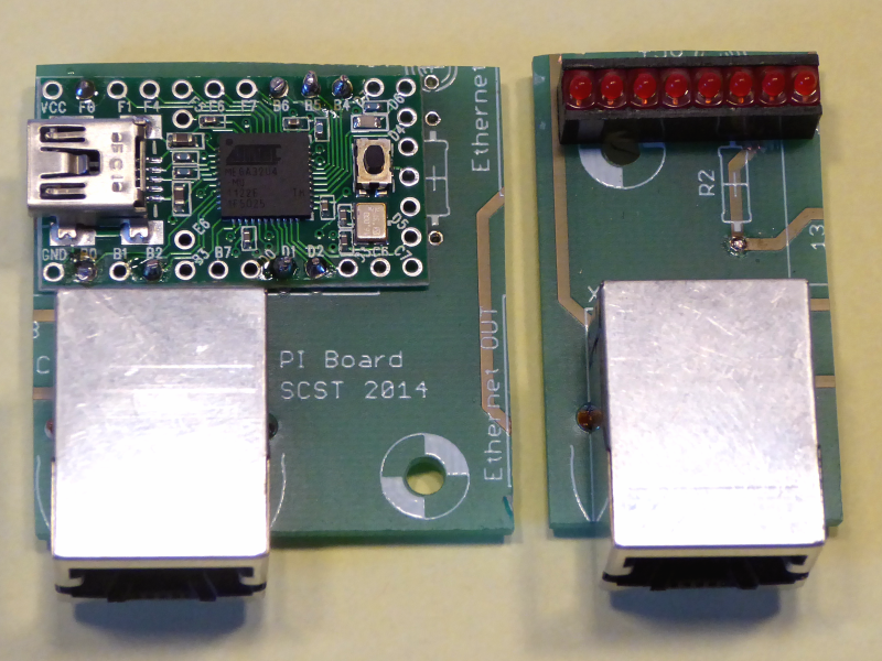
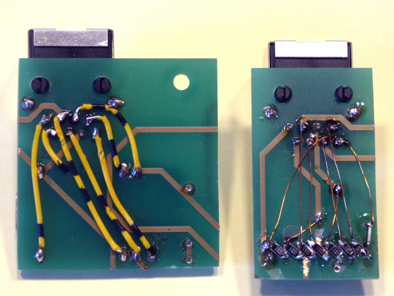
I had an old damaged PCB (Jean or Bob do you recognise it?) and recycled the PCB.
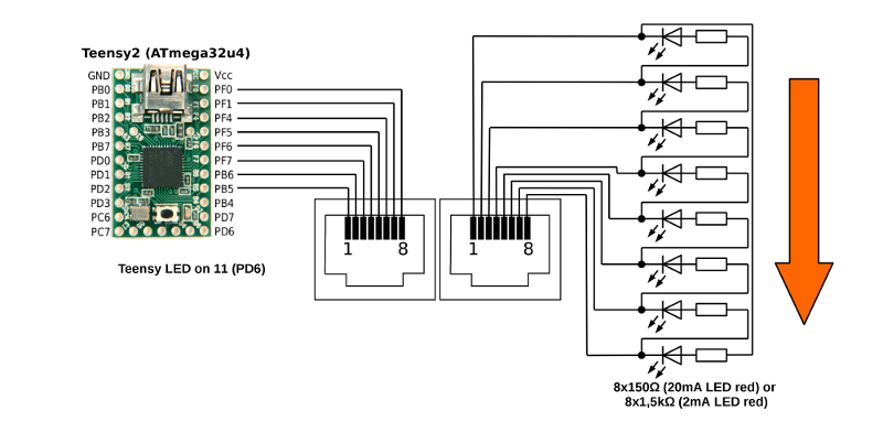
The circuits and the software is very basic. For the first board you
connect 8 Pins from an Arduino (here a Teensy 2.0)
to an RJ45 connector.
The second board gets 8 LEDs with series resistances. All LEDs and
resistances are connected in series (LED-resistance-LED-resistance etc.). The 8
pins of the RJ45 connector are connected to the cathodes.
Pay attention on the direction (1 to 8) of your pins! If your Ethernet cable is twisted, the connection will not work!
Program
The arduino programm is very simple:
    //  simple cable tester with teensy 2.0
    //  Turns on an 8 LEDs on for one second.
    //  www.weigu.lu/cable_tester
    //  This example code is in the public domain.

    const byte TeensyLED = 11;
    const byte LED1 = 21;
    const byte LED2 = 20;
    const byte LED3 = 19;
    const byte LED4 = 18;
    const byte LED5 = 17;
    const byte LED6 = 16;
    const byte LED7 = 15;
    const byte LED8 = 14;

    const byte LEDs[8] = {LED1,LED2,LED3,LED4,LED5,LED6,LED7,LED8};

    void SetLED(byte pin, int ms) {
    digitalWrite(pin, HIGH);
    delay(ms);
    digitalWrite(pin, LOW);}

    void setup() {
    pinMode(TeensyLED, OUTPUT);
    for (byte i = 0;i < 8;i++) {
        pinMode(LEDs[i], OUTPUT);}}

    void loop() {
    for (byte i = 0;i < 8;i++) {
        digitalWrite(TeensyLED, HIGH);
        SetLED(LEDs[i],1000);
        digitalWrite(TeensyLED, LOW);
        delay(500);}}
Download
Arduino Program (cable_tester.ino)
Video


