Microcontroller projects
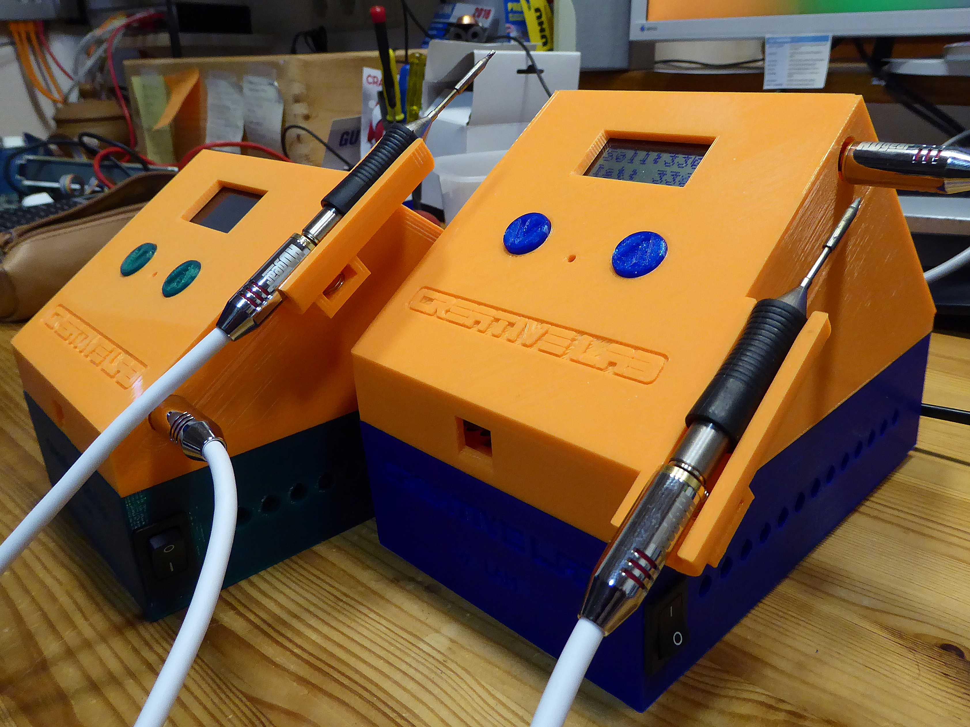
Creative Lab RT soldering station
last updated: 2021-10-29
Short description
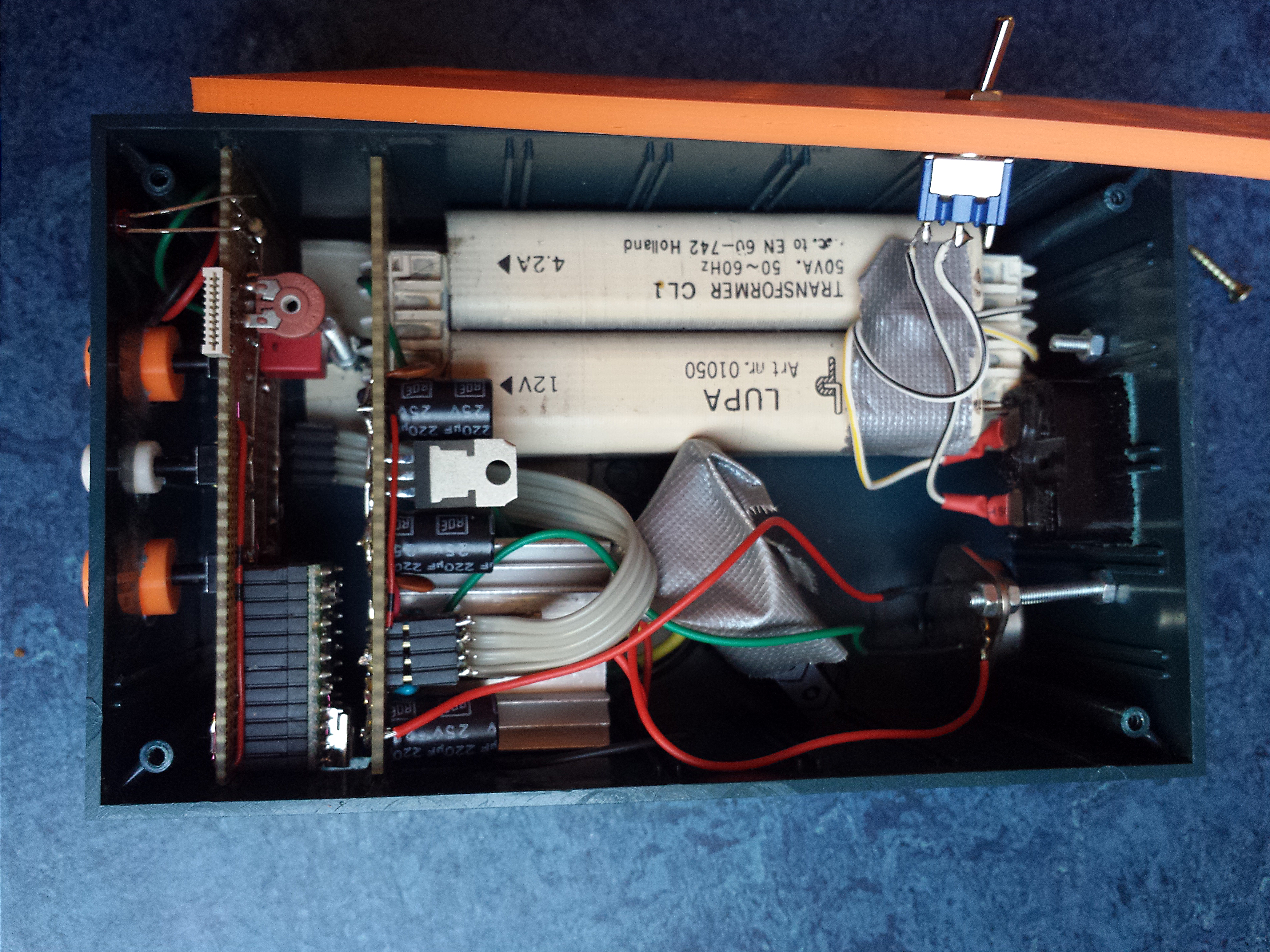
After reading an article from Martin Kumm about an SMD soldering station in the German ham-magazine Funkamateur I decided to build my own station with my beloved Teensy-Board ;) (see Teensyduino). The station uses active soldering tips from Weller (RT series) which contains the heating element as well as a sensor and provide a standard 3.5 mm jack. With these tips SMD soldering is really easy. The SMD soldering station has a very fast heat up time.
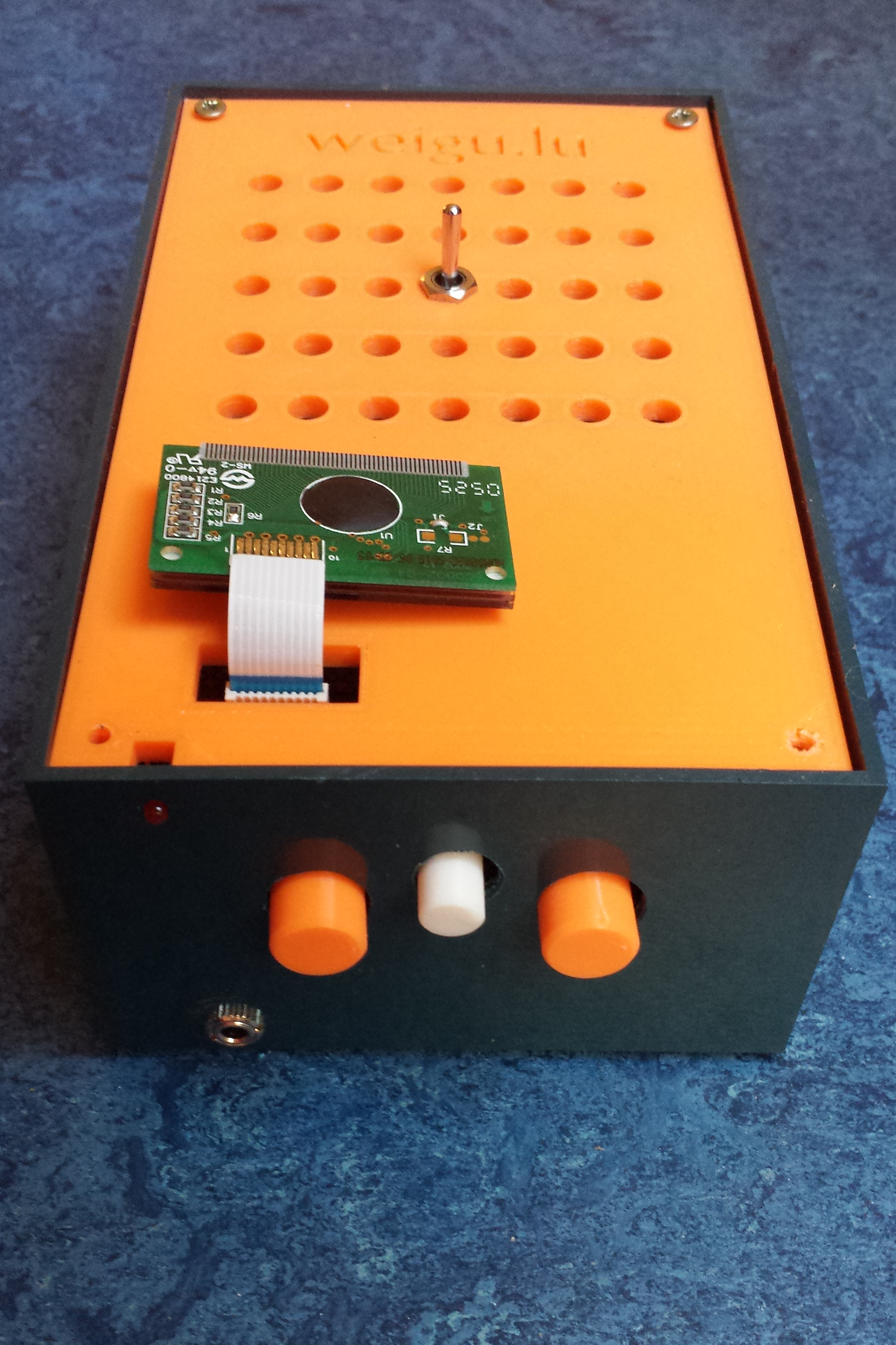
I'm using a cheap 8*2 LCD Display from Pollin.de but all other HD44780 compatible display will do the job.
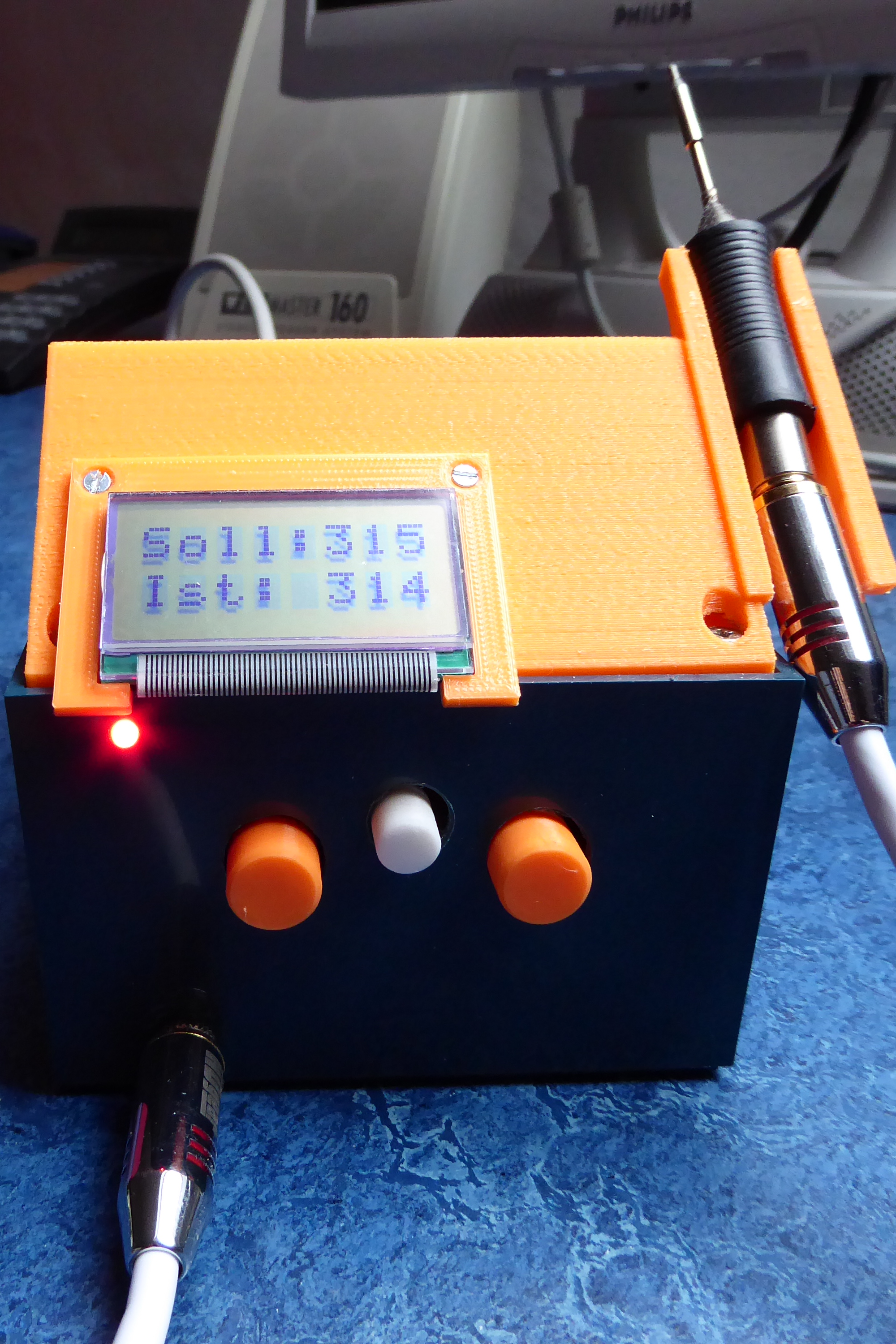
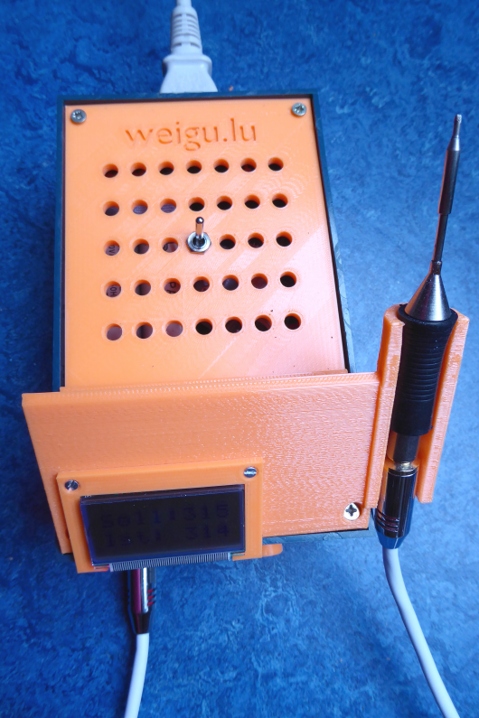
The Arduino code was changed to match all the circuit changes. The housing was printed with my Felix. The two pushbuttons are needed to adjust the temperature. A contact spring in the housing is for standby (50′C).
After my first prototype (bottom of the page) I had the idea to create a workshop for teachers on SMD soldering, Arduino and 3D-printing. Three more prototypes later the workshop is running (March 016) in our new creative-lab. The circuit is based on an Arduino Leonardo or Micro (mega32u4 same as Teensy) because the Teensy bootloader is not open source. A document written together with Bob Fisch is explaining all the details (sorry in German).
German documentation (pdf)
The 4 prototypes
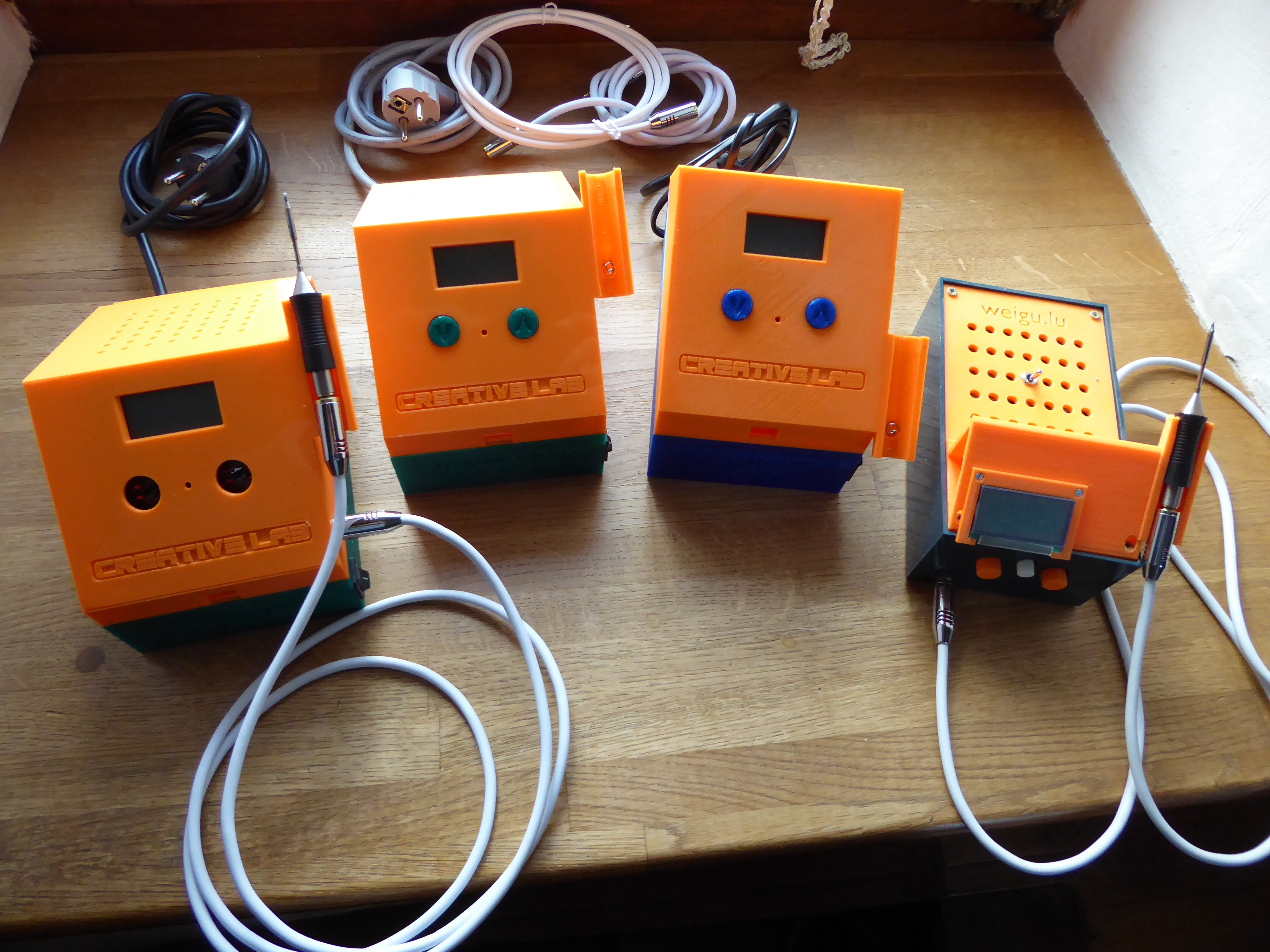
Jean Claude's Plexiglas version (everything CNC)

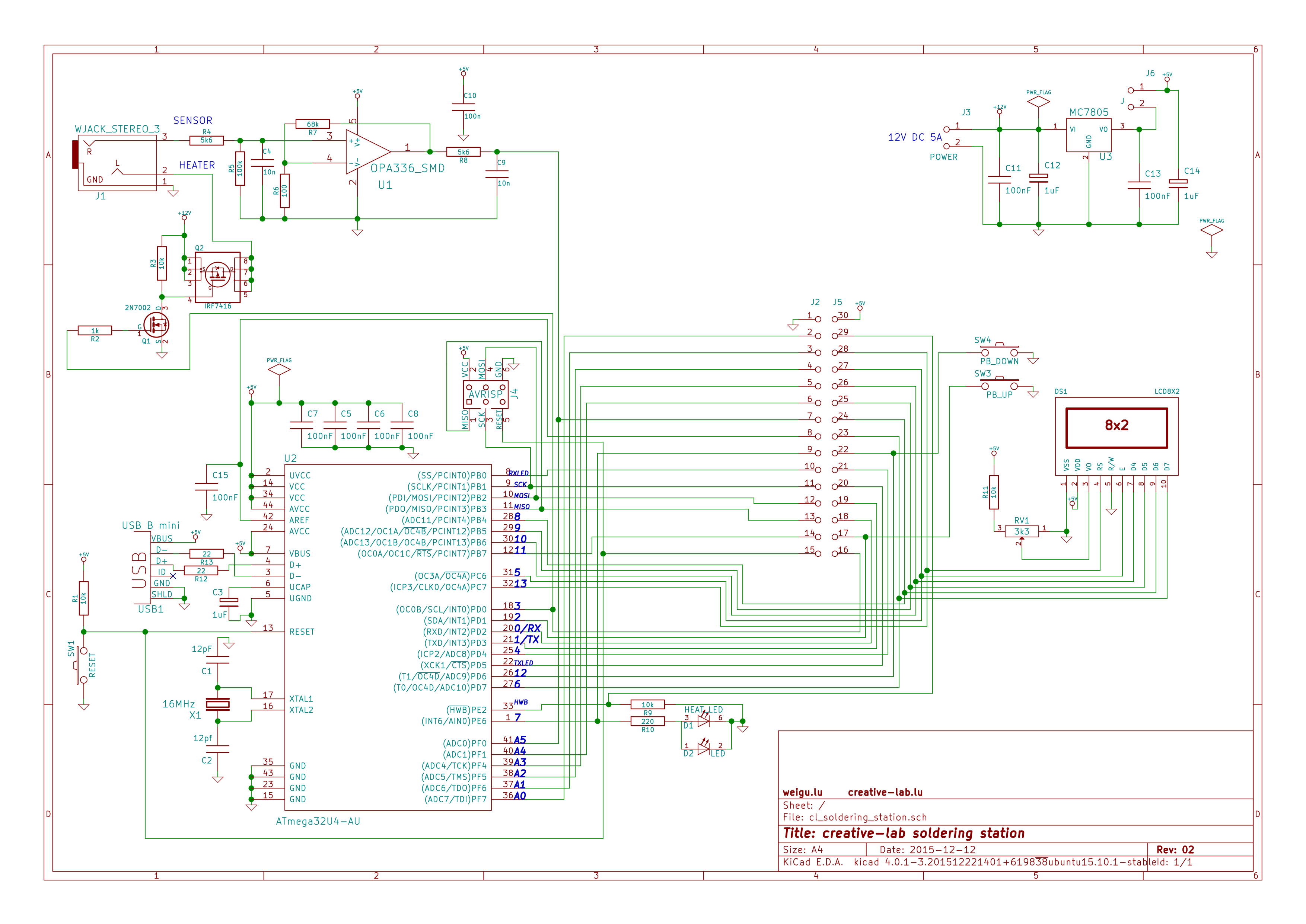
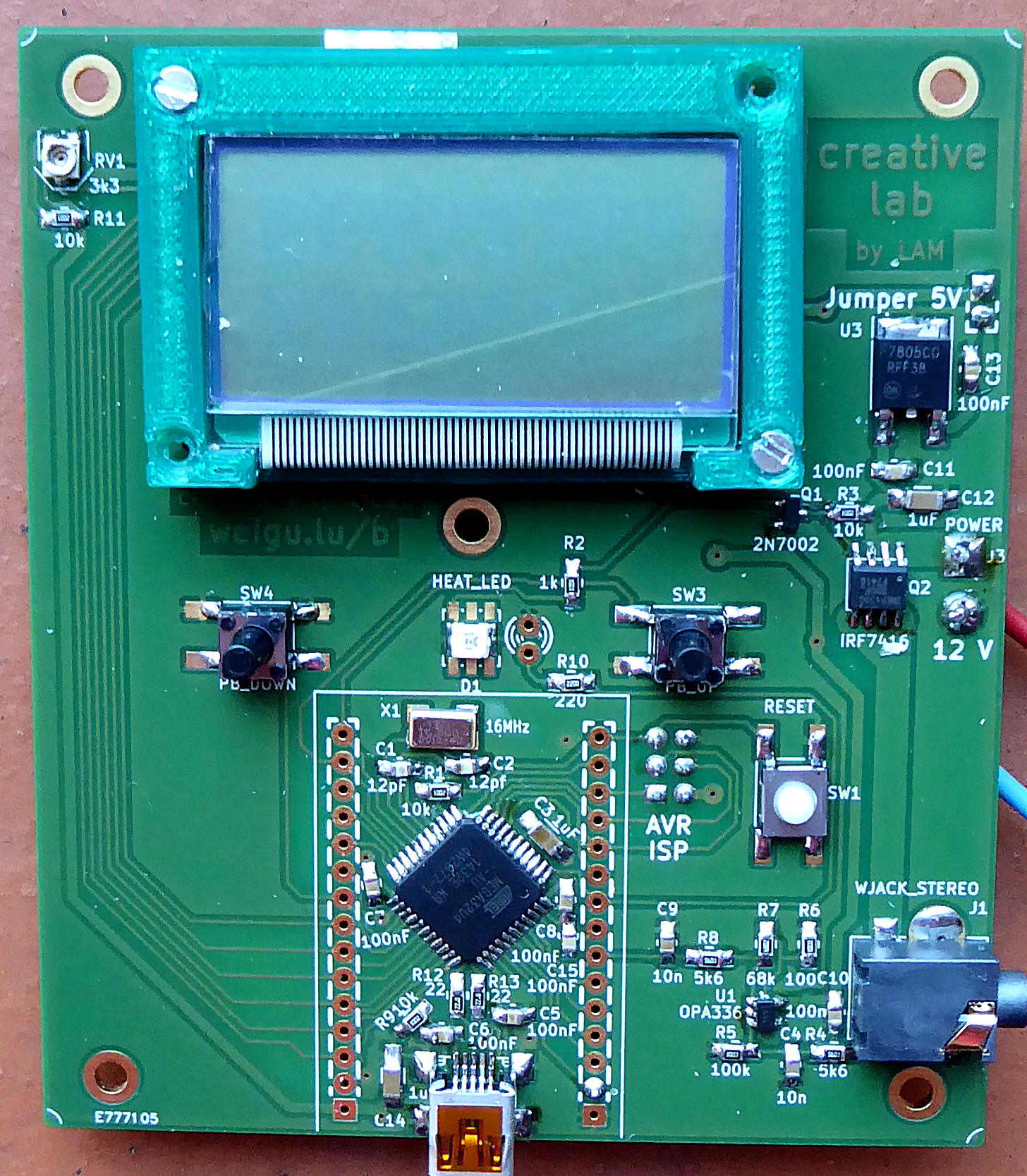
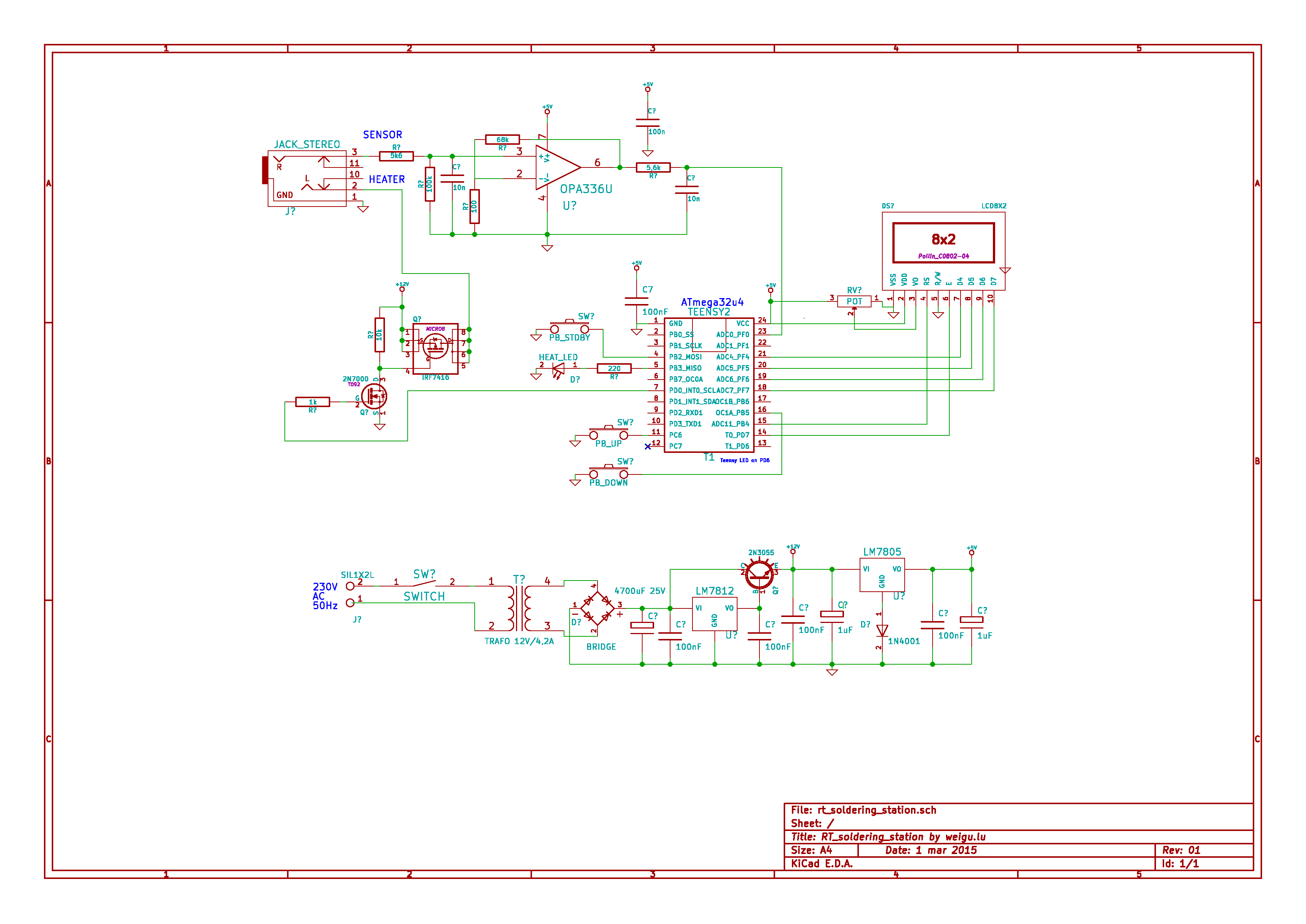
Circuit
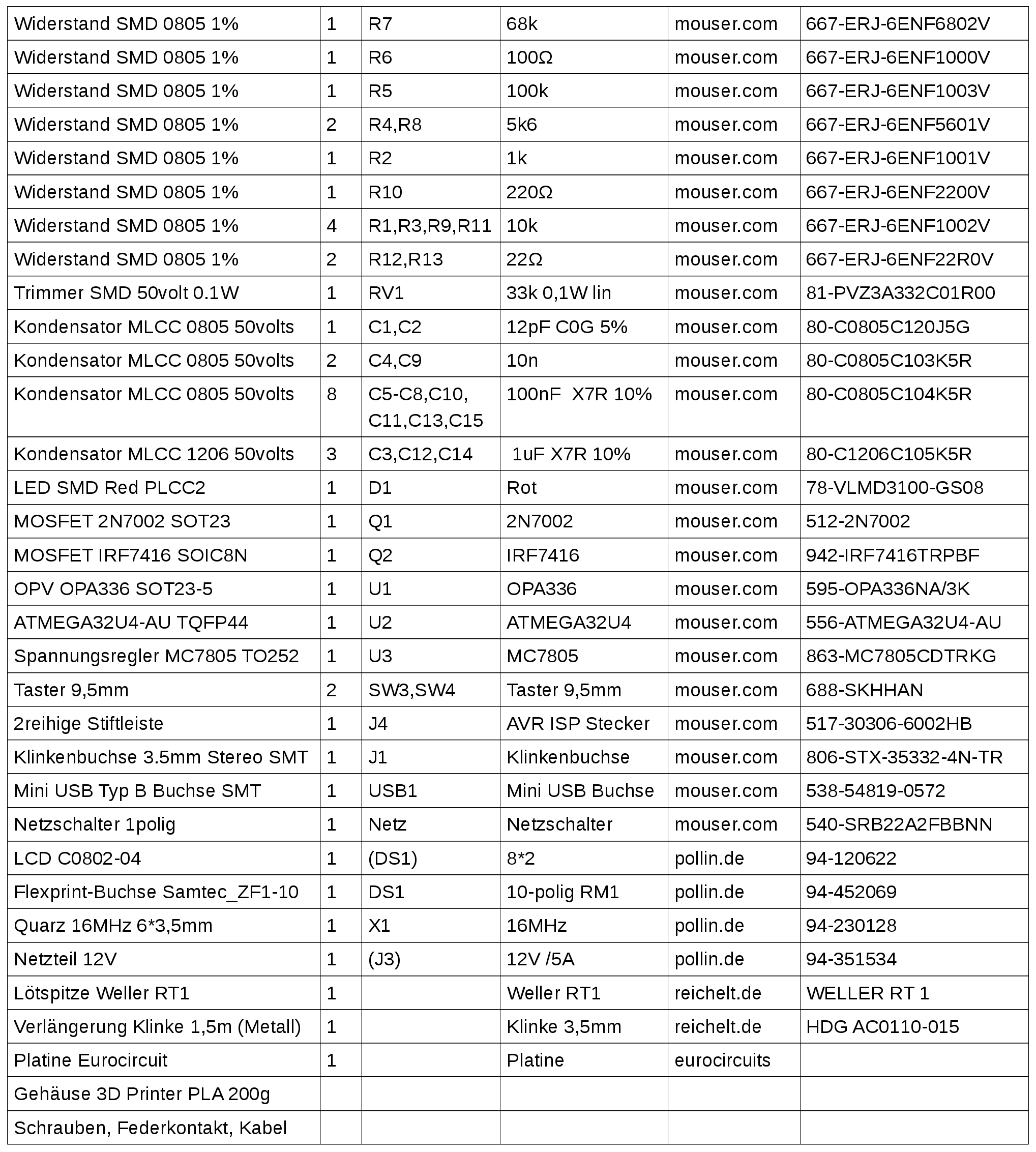
BOM
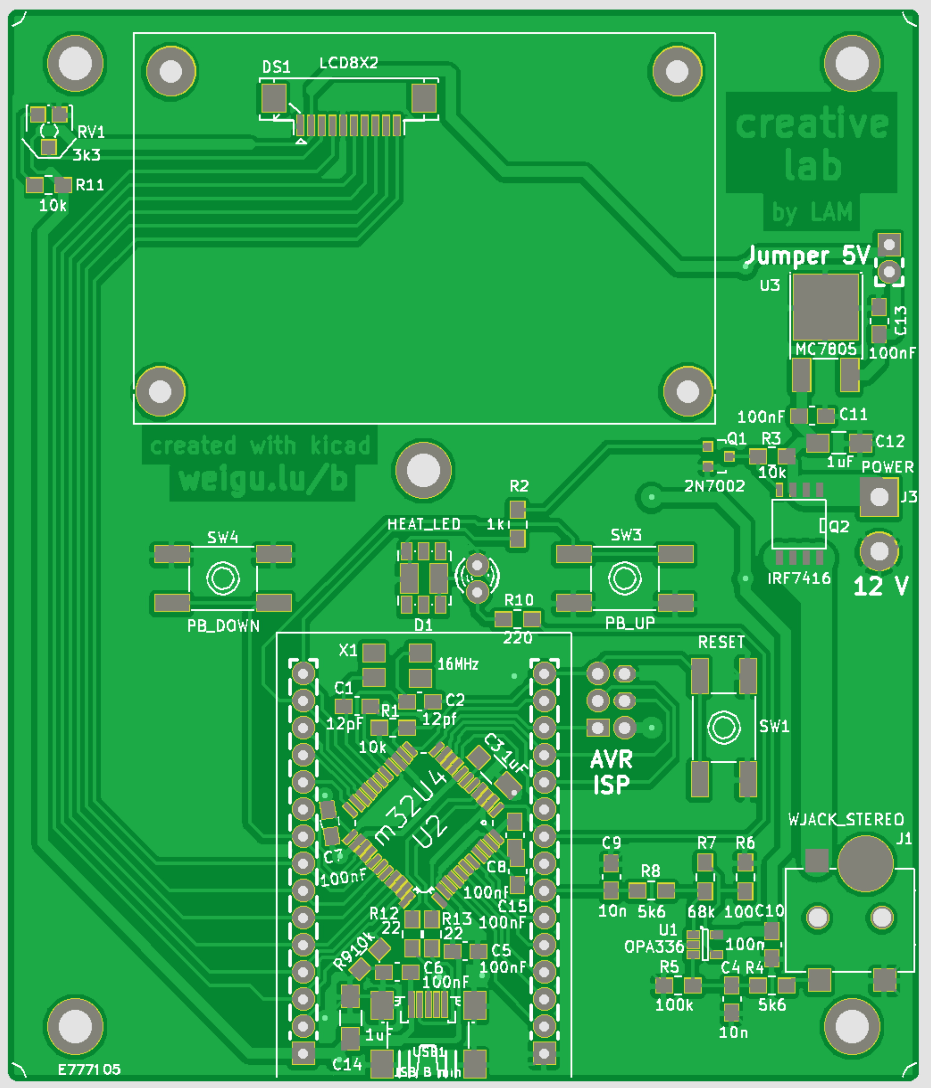
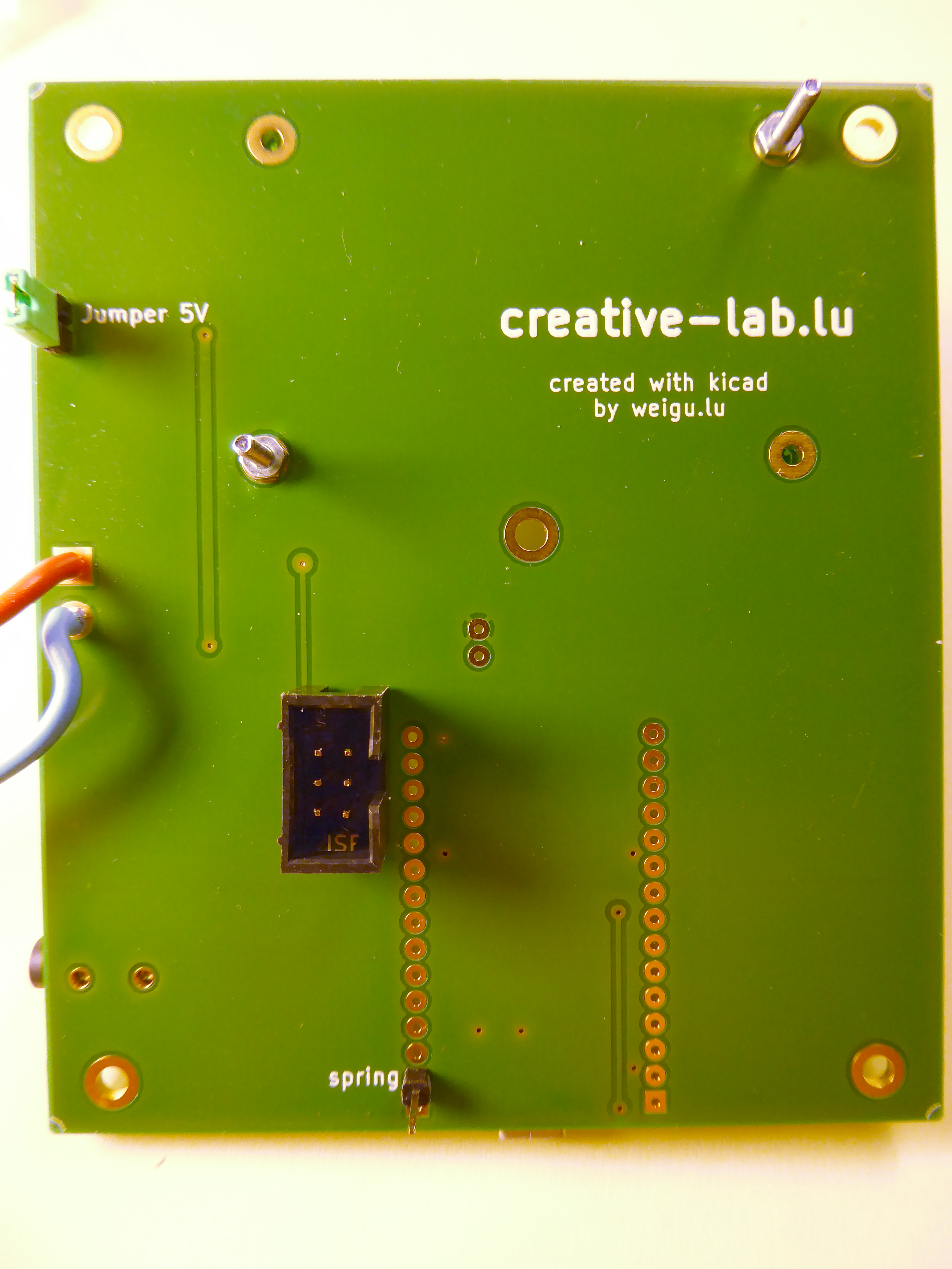
PCB
The PCB is principally one sided with 6 wire straps. It was drawn with Kicad and all the files are available here:
SMD soldering
Look at this awesome video from Jean Daubenfeld (double click to enlarge):
CLEO
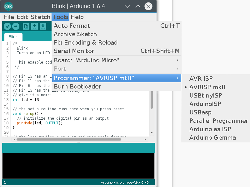
One part of the circuit is based on an Arduino Leonardo or Micro (mega32u4 same as Teensy) and named Creative-Lab lEOnardo or CLEO. After the soldering of the board the ATMEL bootloader is overridden with the Leonardo bootloader. To do this select Leonardo-Board in the Arduino IDE, connect an AVRISP mk2 (or another Arduino) to the ISP connector on the back and press burn bootloader.
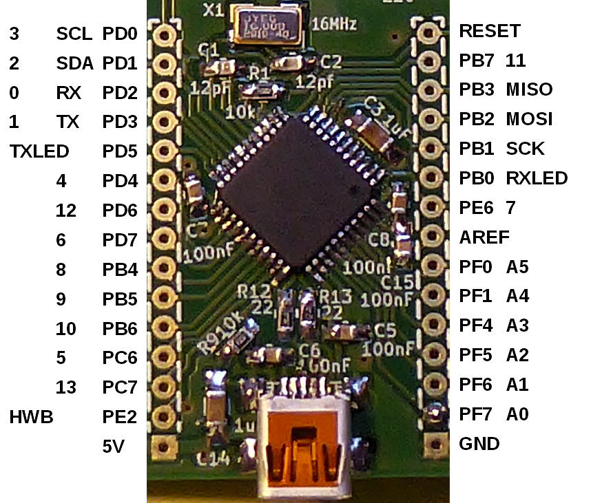
On the PCB the following Arduino Pins are free for Mods: 0, 1, 4, 11, A1, A2,A3 und A4. Here some Mods from Bob:
CLEO pinmapping

Software
Software
The software is a course to learn Arduino programming. I tried to keep it as simple as possible. The first sketch is for testing the LED, the second sketch uses the LCD. In the third sketch the the push-buttons and the spring contact for standby are tested. The fourth sketch is for testing the ADC-circuit. The final sketch is the whole firmware (with PWM).:
cl_ss_LED_test.ino
/* cl_ss_LED_test.ino
Blinking LED (1Hz) */

// Pin 7 has an LED connected on the creative-lab soldering board
const byte led = 7;

void setup() {               // the setup routine runs once
  pinMode(led, OUTPUT);}     // initialize the digital pin as an output.

void loop() {                // the loop routine runs over and over again forever
  digitalWrite(led, HIGH);   // turn the LED on (HIGH is the voltage level)
  delay(500);                // wait for 500ms
  digitalWrite(led, LOW);    // turn the LED off by making the voltage LOW
  delay(500);}               // wait for 500ms
cl_ss_LCD_test.ino
/* cl_ss_LCD_test.ino
Testing the Pollin 8*2 Display on the creative-lab soldering board. */

#include <LiquidCrystal.h>


const byte led = 7; // PE6 LED Arduino-Micro Pin 7

// initialize the library with the numbers of the LCD pins
// LiquidCrystal(rs, enable, d4, d5, d6, d7)
// PC7, PC6, PB6, PB5, PB4, PD7: 13, 5, 10, 9, 8, 6
LiquidCrystal lcd(13, 5, 10, 9, 8, 6);

void setup() {
  pinMode(led, OUTPUT);      // initialize the digital pin 7 as an output
  lcd.begin(8,2);            // set up the LCD's number of columns and rows
  lcd.print("CREATIVE");     // print a message to the LCD.
  lcd.setCursor(0,1);        // cursor position to sedond row
  lcd.print("  LAB");
  delay(2000);
  lcd.clear();
  lcd.setCursor(0,0);
  lcd.print(" LOET-");
  lcd.setCursor(0,1);
  lcd.print("STATION");}

void loop() {
  digitalWrite(led, HIGH);   // turn the LED on
  delay(500);                // wait for 500ms
  digitalWrite(led, LOW);    // turn the LED off
  delay(500);}               // wait for 500ms
cl_ss_button_test.ino
/* cl_ss_button_test.ino
Testing the buttons on the creative-lab soldering board */

#include <LiquidCrystal.h>

const byte led = 7;            // PE6 LED  Arduino-Micro Pin 7
const byte pbUp = 2;           // PD1 UP   Arduino-Micro Pin 2
const byte pbDown = 12;        // PD6 DOWN Arduino-Micro Pin 12
const byte pinStandby = A0;    // PF7 STANDBY Arduino-Micro Pin A0

// initialize the library with the numbers of the LCD pins
// LiquidCrystal(rs, enable, d4, d5, d6, d7)
// PC7, PC6, PB6, PB5, PB4, PD7: 13, 5, 10, 9, 8, 6
LiquidCrystal lcd(13, 5, 10, 9, 8, 6);

int targetTemp;
int actualTemp;
int targetTempPb;
const int targetTempIni = 350;
const int standbyTemp = 50;
const int maxTemp = 420;
const int mainLoopDelay = 10;  // respond time of pushbuttons and heating!

void setup() {
  pinMode(led, OUTPUT);         // initialize the digital pin 7 as an output
  pinMode(pbUp, INPUT_PULLUP);  // 3*PB with internal pullup
  pinMode(pbDown, INPUT_PULLUP);
  pinMode(pinStandby, INPUT_PULLUP);
  LCD_ini();           // function to initalize the display (see below)
  targetTemp = targetTempIni;
  targetTempPb = targetTempIni; }

void loop() {
  actualTemp = 25;
  LCD_update();            // function to update the display (see below)
  pushbutton_control();        // funct. to increment and decr. the temperature
  delay(mainLoopDelay); }

// function to increment and decrement the temperature
void pushbutton_control() {
  if (digitalRead(pbUp)==LOW) { // change temp if one of the pushbuttons
    targetTempPb++;        // is pressed and control max and min values
    if (targetTempPb > maxTemp) targetTempPb = maxTemp; }
  if (digitalRead(pbDown) == LOW) {
    targetTempPb--;
    if (targetTempPb < 25) targetTempPb = 25; }
  if (digitalRead(pinStandby) == LOW) targetTemp = standbyTemp;
  else targetTemp = targetTempPb; }

// function to update the changing values on the display
void LCD_update() {
  lcd.setCursor(5,0);
  lcd.print("000");
  if (targetTemp <100) lcd.setCursor(6,0);
  else lcd.setCursor(5,0);
  lcd.print(targetTemp);
  lcd.setCursor(5,1);
  lcd.print("000");
  if (actualTemp <100) lcd.setCursor(6,1);
  else lcd.setCursor(5,1);
  lcd.print(actualTemp); }

// function with welcome text and initialization of the constant text
void LCD_ini() {
  lcd.begin(8,2);               // set up the LCD's number of columns and rows
  lcd.print("CREATIVE");        // print a message to the LCD.
  lcd.setCursor(0,1);           // cursor position to second row
  lcd.print("  LAB");           // ...
  delay(2000);
  lcd.clear();
  lcd.setCursor(0,0);
  lcd.print(" LOET-");
  lcd.setCursor(0,1);
  lcd.print("STATION");
  delay(2000);
  lcd.clear();
  lcd.print("Soll:");
  lcd.setCursor(0,1);
  lcd.print("Ist: "); }
cl_ss_ADC_test.ino
/* cl_ss_ADC_test.ino
Testing the ADC input on the creative-lab soldering board */

#include <LiquidCrystal.h>

const byte led = 7;            // PE6 LED  Arduino-Micro Pin 7
const byte pbUp = 2;           // PD1 UP   Arduino-Micro Pin 2
const byte pbDown = 12;        // PD6 DOWN Arduino-Micro Pin 12
const byte pinStandby = A0;    // PF7 STANDBY Arduino-Micro Pin A0
const byte pinTemp = A5;       // PF0 ADC Arduino-Micro Pin A5

// initialize the library with the numbers of the LCD pins
// LiquidCrystal(rs, enable, d4, d5, d6, d7)
// PC7, PC6, PB6, PB5, PB4, PD7: 13, 5, 10, 9, 8, 6
LiquidCrystal lcd(13, 5, 10, 9, 8, 6);

int targetTemp;
int actualTemp;
int targetTempPb;

const int   targetTempIni = 350;
const int   standbyTemp = 50;
const int   maxTemp = 420;
const int   mainLoopDelay = 10;    // respond time of pushbuttons and heating!
const int   adcDelay = 10;       // delay before measure in ms
const float adcGain = 0.45;    // R2=68K
const float adcOffset = 25;

void setup() {
  pinMode(led, OUTPUT);         // initialize the digital pin 7 as an output
  pinMode(pbUp, INPUT_PULLUP);  // 3*PB with internal pullup
  pinMode(pbDown, INPUT_PULLUP);
  pinMode(pinStandby, INPUT_PULLUP);
  LCD_ini();           // function to initalize the display (see below)
  targetTemp = targetTempIni;
  targetTempPb = targetTempIni; }

void loop() {
  actualTemp = getTemp();
  LCD_update();            // function to update the display (see below)
  pushbutton_control();        // funct. to increment and decr. the temperature
  delay(mainLoopDelay); }

// function read the temperature (ADC)
int getTemp() {
  unsigned int adcValue = analogRead(pinTemp); // read the input on analog pin
  return round(((float) adcValue)*adcGain+adcOffset); } // calculate temperature

// function to increment and decrement the temperature
void pushbutton_control() {
  if (digitalRead(pbUp)==LOW) { // change temp if one of the pushbuttons
    targetTempPb++;        // is pressed and control max and min values
    if (targetTempPb > maxTemp) targetTempPb = maxTemp; }
  if (digitalRead(pbDown) == LOW) {
    targetTempPb--;
    if (targetTempPb < 25) targetTempPb = 25; }
  if (digitalRead(pinStandby) == LOW) targetTemp = standbyTemp;
  else targetTemp = targetTempPb; }

// function to update the changing values on the display
void LCD_update() {
  lcd.setCursor(5,0);
  lcd.print("000");
  if (targetTemp <100) lcd.setCursor(6,0);
  else lcd.setCursor(5,0);
  lcd.print(targetTemp);
  lcd.setCursor(5,1);
  lcd.print("000");
  if (actualTemp <100) lcd.setCursor(6,1);
  else lcd.setCursor(5,1);
  lcd.print(actualTemp); }

// function with welcome text and initialization of the constant text
void LCD_ini() {
  lcd.begin(8,2);               // set up the LCD's number of columns and rows
  lcd.print("CREATIVE");        // print a message to the LCD.
  lcd.setCursor(0,1);           // cursor position to second row
  lcd.print("  LAB");           // ...
  delay(2000);
  lcd.clear();
  lcd.setCursor(0,0);
  lcd.print(" LOET-");
  lcd.setCursor(0,1);
  lcd.print("STATION");
  delay(2000);
  lcd.clear();
  lcd.print("Soll:");
  lcd.setCursor(0,1);
  lcd.print("Ist: "); }
cl_ss_firmware.ino
/* cl_ss_firmware.ino
firmware for the creative-lab soldering board */

#include <LiquidCrystal.h>

const byte led = 7;            // PE6 LED  Arduino-Micro Pin 7
const byte pbUp = 2;           // PD1 UP   Arduino-Micro Pin 2
const byte pbDown = 12;        // PD6 DOWN Arduino-Micro Pin 12
const byte pinStandby = A0;    // PF7 STANDBY Arduino-Micro Pin A0
const byte pinTemp = A5;       // PF0 ADC Arduino-Micro Pin A5
const byte pwmOut = 3;         // PD0 pwmOut Arduino-Micro Pin 3

// initialize the library with the numbers of the LCD pins
// LiquidCrystal(rs, enable, d4, d5, d6, d7)
// PC7, PC6, PB6, PB5, PB4, PD7: 13, 5, 10, 9, 8, 6
LiquidCrystal lcd(13, 5, 10, 9, 8, 6);

int targetTemp;
int actualTemp;
int targetTempPb;
int pwm;

const int   targetTempIni = 350;
const int   standbyTemp = 50;
const int   maxTemp = 420;
const int   mainLoopDelay = 5;  // respond time of pushbuttons and heating!
const int   adcDelay = 10;      // delay before measure in ms (low pass filter)
const float adcGain = 0.45;     // R1=100 R2=68K adcGain = 5V/1023/680/16*10E-6
const float adcOffset = 25;
const int   ctrlGain = 10;      // for pwm to heat faster

void setup() {
  pinMode(led, OUTPUT);         // initialize the pin for the led as an output
  pinMode(pbUp, INPUT_PULLUP);  // 3*PB with internal pullup
  pinMode(pbDown, INPUT_PULLUP);
  pinMode(pinStandby, INPUT_PULLUP);
  pinMode(pwmOut, OUTPUT); // PWM output
  LCD_ini();           // function to initalize the display (see below)
  targetTemp = targetTempIni;
  targetTempPb = targetTempIni;
  pwm=0; }         // dont heat up immediatly

void loop() {
  actualTemp = getTemp();
  automatic_control();
  LCD_update();            // function to update the display (see below)
  pushbutton_control();        // funct. to increment and decr. the temperature
  delay(mainLoopDelay); }

// function for automatic control (P controller)
void automatic_control() {
  int diff = targetTemp-actualTemp; // get difference
  pwm = diff*ctrlGain;     // heat up faster
  if(pwm > 255) pwm = 255;       //limit pwm value to 0...255
  if (actualTemp > targetTemp) pwm = 0;
  analogWrite(pwmOut, pwm);
  if(pwm > 0) digitalWrite(led, HIGH); //set heat LED
  else digitalWrite(led, LOW); }

// function read the temperature (ADC)
int getTemp() {
  analogWrite(pwmOut, 0);      // switch off heater
  delay(adcDelay);     // wait for low pass filter (steady state)
  unsigned int adcValue = analogRead(pinTemp); // read the input on analog pin
  analogWrite(pwmOut, pwm);
  return round(((float) adcValue)*adcGain+adcOffset); } // calculate temperature

// function to increment and decrement the temperature
void pushbutton_control() {
  if (digitalRead(pbUp)==LOW) { // change temp if one of the pushbuttons
    targetTempPb++;        // is pressed and control max and min values
    if (targetTempPb > maxTemp) targetTempPb = maxTemp; }
  if (digitalRead(pbDown) == LOW) {
    targetTempPb--;
    if (targetTempPb < 25) targetTempPb = 25; }
  if (digitalRead(pinStandby) == LOW) targetTemp = standbyTemp;
  else targetTemp = targetTempPb; }

// function to update the changing values on the display
void LCD_update() {
  lcd.setCursor(5,0);
  lcd.print("000");
  if (targetTemp <100) lcd.setCursor(6,0);
  else lcd.setCursor(5,0);
  lcd.print(targetTemp);
  lcd.setCursor(5,1);
  lcd.print("000");
  if (actualTemp <100) lcd.setCursor(6,1);
  else lcd.setCursor(5,1);
  lcd.print(actualTemp); }

// function with welcome text and initialization of the constant text
void LCD_ini() {
  lcd.begin(8,2);               // set up the LCD's number of columns and rows
  lcd.print("CREATIVE");        // print a message to the LCD.
  lcd.setCursor(0,1);           // cursor position to second row
  lcd.print("  LAB");           // ...
  delay(2000);
  lcd.clear();
  lcd.setCursor(0,0);
  lcd.print(" LOET-");
  lcd.setCursor(0,1);
  lcd.print("STATION");
  delay(2000);
  lcd.clear();
  lcd.print("Soll:");
  lcd.setCursor(0,1);
  lcd.print("Ist: "); }
Downloads:
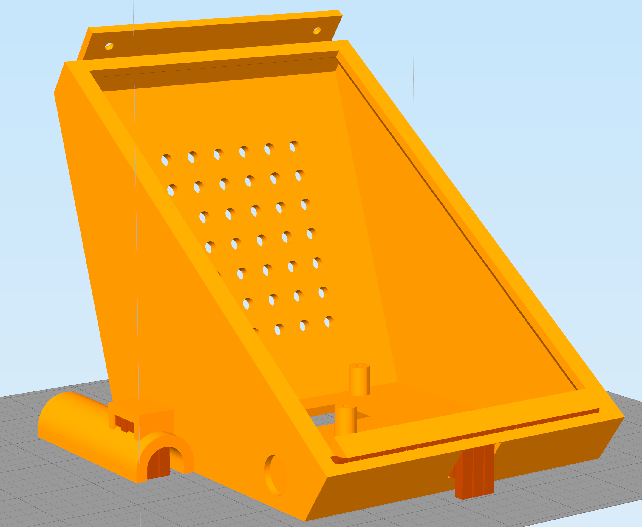
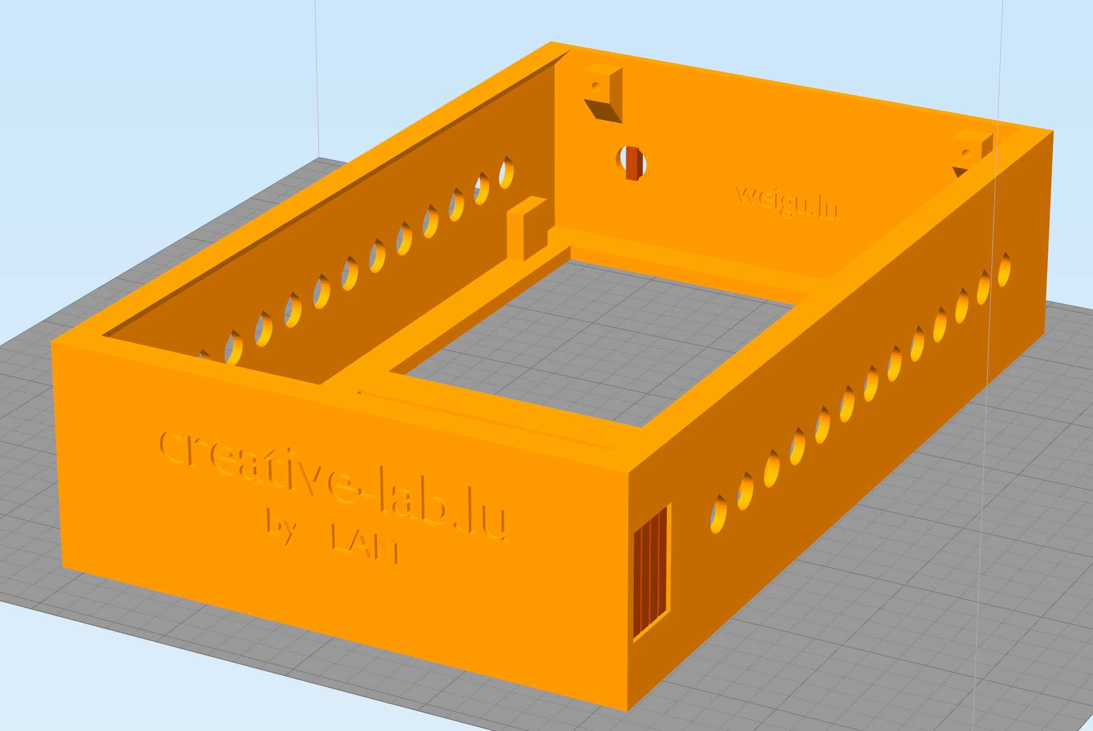
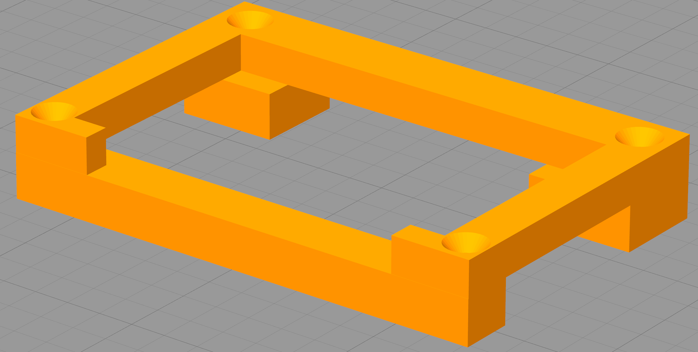
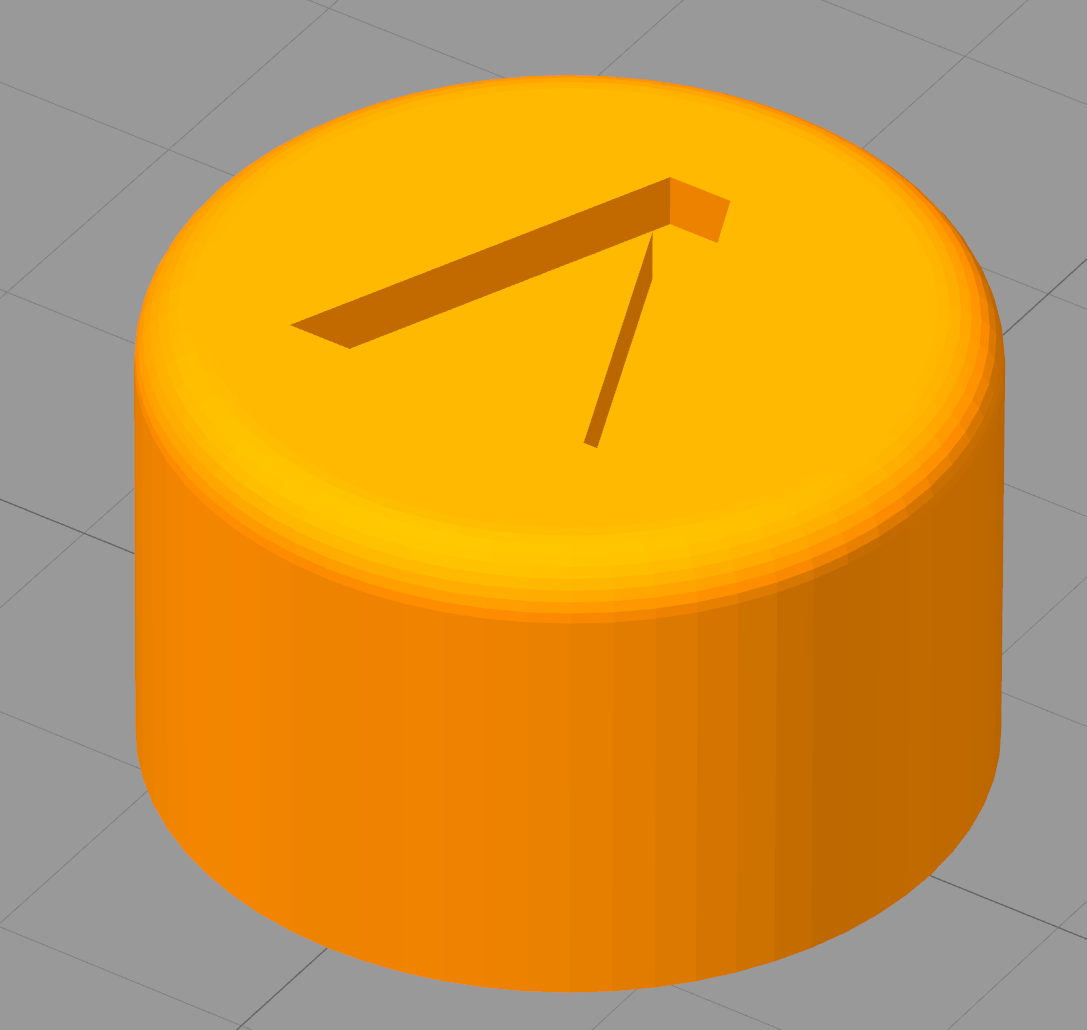
3D printing
The 3D housing was created with blender and has 5 parts (top, bottom, LCD holder and 2 buttons). For more infos on assembling the station see the pictures in:
- cl_ss_top_case_v3_final.stl
- cl_ss_bottom_case_v3_final.stl
- cl_ss_LCD_holder_v2_final.stl
- cl_ss_knob.stl
Old Prototype
Software for the old prototype:
Teensyduino: rt_solder_station_weigu_v1_0.ino
