Microcontroller projects
Creative-lab space mining rover: Snyder 1
last updated: 2021-11-02
Quick links
- Einleitung / Introduction
- Montageanleitung / Assembly instructions
- Materiallliste / Bill of materials (BOM)
- Mechanische Teile montieren / Mechanics
- Platine bestücken und löten / PCB assembling and soldering
- Erster Test / First Test
- Neue Software / New software with slider and websockets
- Schaltplan / Circuit
- Alte Software / Older Software without websockets
- Downloads
- Interesting links:
Einleitung / Introduction
Der Rover lässt sich über das Wifi Netz mit einem PC oder Handy steuern. Er wurde von Jean Daubenfeld und mir für das creative-lab entwickelt und schon 35x auf dem Luxemburgischen Makerfest aufgebaut.
*The rover is WLAN controlled by a computer or phone. The rover was developed by Jean Daubenfeld and myself for the creative-lab and was build 35 times on the 2 Luxemburgish Makerfest.
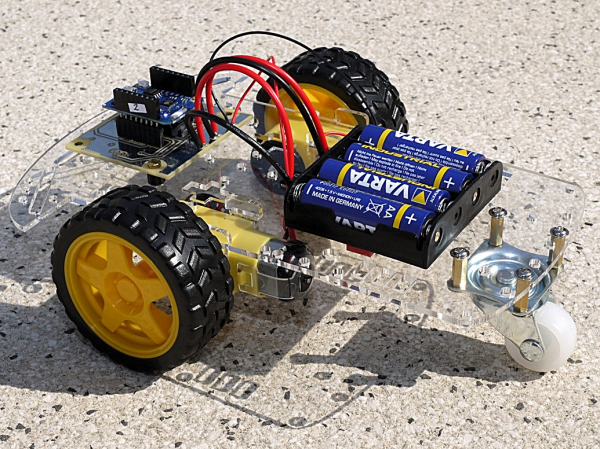
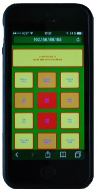
Die Anleitung wurde hauptsächlich von Jean-Claude Feltes erstellt und ist als pdf verfügbar. Jean_Claude hat auch zwei interessante Dokumente zu Software (Englisch) geschrieben, die hier erhältlich sind:
The assembly instructions were written mostly by Jean-Claude Feltes and are available as pdf. Jean claude has also written 2 interesting documents covering the software:
- Bauanleitung (pdf) / assembly instructions (pdf)
- WiFi with the ESP8266, part1: scan WiFi and switch a LED (english)
- WiFi with the ESP8266, part2: display temperature values on a webpage
Montageanleitung / Assembly instructions
Materiallliste / Bill of materials (BOM)
- Roboterchassis (Bausatz) / robot car chassis (kit)
- Mikrocontrollerplatine: Wemos D1 mini pro / microcontroller-board: Wemos D1 mini pro
- Creative-lab Platine / PCB from creative-lab (see Downloads)
- IC L293D Motortreiber / IC L293D (motor-driver)
- IC Fassung 16 polig / IC socket 16-pins
- Diode 1N4004 oder 1N4007 / diode 1N4004 or 1N4007
- Roter Plexiglasstreifen 60x10 / red bar 60x10 with 2 holes (washer for the battery holder)
- 2 Schrauben M210 mit Muttern / *2 screws M2x10 + nuts
- 2 Schrauben M3x10 mit Abstandshaltern und Muttern / 2 screws M3x10 ++ nuts + 5mm spacer (to fix the PCB)
- 4 Batterien AA 1,5V / 4 batteries AA alkaline 1,5V
Mechanische Teile montieren / Mechanics
Achtung: Bei den meisten Teilen ist es wichtig, in welche Richtung man sie dreht! Um frustrierendes Wieder-Auseinandernehmen zu vermeiden, sollte man jeden Schritt genau überlegen.
Most parts have to be mounted in the right direction. It is frustrating to unmount parts that are not mounted the right way, so stay concentrated and look twice at the pictures.
Dein Bausatz sollte diese Teile enthalten (parts from your kit:):
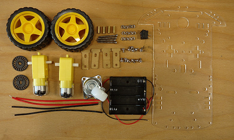
Entferne die Schutzfolie bzw. Papier von den Plexiglasteilen.
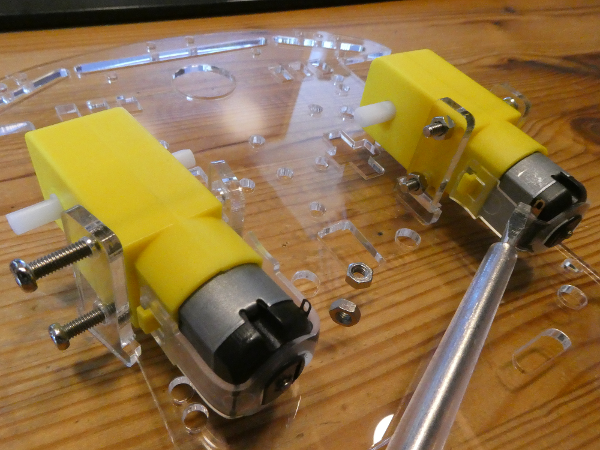
Remove the protective film or paper from the acrylic glass plates.Montiere die Motoren. Du benötigst 4 M3x30 Schrauben und 4 M3 Muttern.
Achte darauf, dass die Kontakte beider Motoren (siehe Schraubendreher-Spitze) nach innen zeigen!
Mount the 2 motors. You need 4 M3x30 screws an 4 M3 nuts. Pay attention to turn the motor contacts to the insight (see screwdriver tip). The acrylic holders can break very easily so be gentle :).
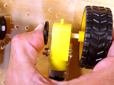
Stecke die Encoderscheiben (schwarze Schlitzscheiben) sowie die Räder auf den Motor.
Vorsicht! Die Plexiglashalter brechen leicht ab! Am besten den Motor gut dabei festhalten, so dass keine Kraft auf die Halterung wirkt.
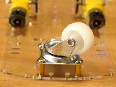
Fix the wheels and encoder disks. The acrylic holders can break very easily so be gentle :).Montiere das Vorderrad mit 4 Abstandshaltern M3x12 und 8 Schrauben M3x6.
Mount the front wheel (4 spacer M3x12, 8 screws M3x6).
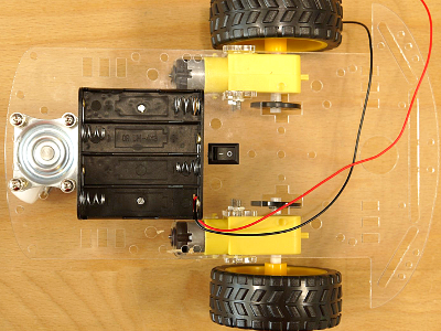
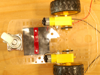
Drehe die Platte um und montiere den Batteriehalter. Dieser wir mit 2 M2-Schrauben befestigt. Der kleine rechteckige Streifen 60x10 mit 2 Bohrungen dient dabei als Unterlegscheibe für die Muttern (unten).
Turn the chassis to mount the battery holder. It is fixed with 2 M2 screws. The red bar (60x10) with 2 holes is used as washer for the 2 nuts (mounted under the chassis).Drücke den Schalter in die rechteckige Öffnung neben dem Batteriehalter.
Push the switch in the square hole (click) near the battery holder.
Platine bestücken und löten / PCB assembling and soldering
Löten / Soldering
Zum Löten gibt es viele gute Seiten und Videos im Netz. Hier eine gute Einführung:
There are many sites and videos on the net, so I will not reinvent the wheel. Here is a good link, explaining soldering:
https://www.sciencebuddies.org/science-fair-projects/references/how-to-solder
- Löte die Diode 1N4004 (oder ähnlich) ein. Achte auf die Polung, der silberne Ring ist auf der Platine markiert.
Beginn by soldering the diode 1N4004 (or 1N4007). Pay attention, the diode has a polarity. The cathode (silver ring) is on the left (white ring on the PCB).*
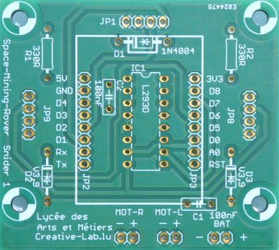
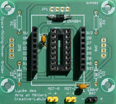
Löte den IC-Sockel ein. Achtung: die Kerbe muß zur Diode hin zeigen. Am besten fängt man mit 2 Pins an, die einander diagonal gegenüber liegen. Dann kontrolliert man ob der Sockel flach aufliegt. Wenn nicht, kann man einen Pin nochmal erhitzen und die Position korrigieren. Dann verlötet man die restlichen Pins.
Next is the IC socket. It has to be turned the right way. It has a little notch on one side. The notch can also be seen on the PCB (top under the diode). First solder 2 pins at the edges. We control that the socket sits flat on the surface. If not we correct this by reheating the pins. Afterwards we solder the remaining pins.Die zwei Kondensatoren im Bild (100nF) und die 3 Stecker sind optional und nicht im Bausatz enthalten.
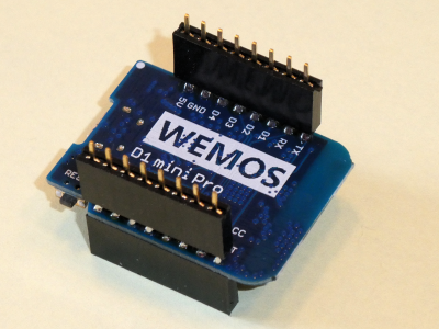
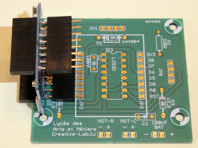
The two capacitors and the 3 header are optional and not included in the kit. +- Stecke die 2 Buchsenleisten auf die Pins der WEMOS-Platine auf. Stecke die WEMOS-Platine auf und verlöte sie. Am besten lötet man auch hier zuerst 2 diagonal gegenüberliegende Pins, kontrolliert noch einmal und verlötet dann den Rest.
After this we solder the remaining 2 8-pin female headers to our PCB. For this we use the microcontroller board as help (second picture).
Connecting the motors
Löte bei jedem Motor ein rotes und ein schwarzes Stück Draht an. Schwarz zur Plexiglasplatte hin, rot auf der anderen Seite. Am besten verzinnt man zuerst die Kontakte und den Draht, danach lötet man beides zusammen.
Solder a red and a black wire to the motor contacts. The black wire is nearest to the acrylic plate!Die Drähte werden durch die Bohrungen links und rechts vom Schalter geführt.
The wires pass the holes left and right from the switch.
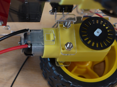
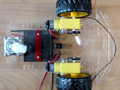
- Die Drähte werden nun mit der Platine verlötet, auf der Seite gegenüber von der Diode. Die 4 Lötaugen rechts sind die Motoranschlüsse (links ist die Spannungsversorgung). Achte auf die Beschriftung.
The wires are soldered to the PCB. Pay attention to the markings on the PCB.
Batterie und Schalter anschließen / Connecting the battery holder and the switch
Zuerst den roten Draht des Batteriehalters (Pluspol) durch eine Bohrung in der Platte zum Schalter führen. Dort den Draht abknipsen und abisolieren und am Schalter verlöten. Das Reststück Draht am anderen Pol des Schalters verlöten und durch die Platte zur Platine führen und dort verlöten. Achte auf die Beschriftung!
Push the red wire of the battery holder (plus) through a hole in the acrylic plate. Shorten the wire and strip the isolation, so we can solder it to the switch. Take the second piece of the wire strip the isolation on two sides and solder it to the second pole of the switch. Get the wire back through the plate to the PCB and solder it to the PCB. Pay attention to the markings on the PCB.Nun den Minuspol des Batteriehalters (schwarz) am zweiten Lötauge verlöten.
The black wire of the battery holder (minus) is soldered to the second pin on the PCB. Pay attention to the markings on the PCB.
Fertigstellung / Finish
Die Platine mit der Lupe noch einmal kontrollieren ob alle Verbindungen korrekt und nirgends ein Kurzschluss ist.
Control all soldering with a magnifying glass. Control all connections and make sure that there is no short circuit.Kontrollieren ob der Schalter auf “Aus” (0) steht.
The switch has to be on "Off" (0).Setze das IC L293D in den Sockel ein. Achtung: die Kerbe muß zur Seite mit der Diode zeigen!
Place the motor-driver IC (L293D) in the socket. The notch has to be on the same side than on the socket (direction of the diode).Stecke die Microcontroller Platine auf. Die USB-Buchse zeigt nach aussen! (zur Diode).
Mount the microcontroller board. The USB connector faces the diode! Mount the microcontroller board. The USB connector faces the diode! (lock at the picture at the top of the page).
Erster Test / First Test
Schalte den Rover ein. Wenn die blaue LED auf dem WEMOS-Chip leuchtet, und der Rover sich kurz nach links dreht, kannst du schon ein wenig optimistisch sein.
Switch the rover on.Suche nun auf deinem Handy nach WiFi-Netzen. Jeder Rover stellt einen eigenen Hotspot zur Verfügung. Er erzeugt also sein eigenes lokales WiFi-Netz, mit seiner eigenen SSID. Die ssid heisst “creativeXX”, wobei XX die zweistellige Nummer deines Rovers ist (Etikette auf der WEMOS-Platine). “creative12” wäre also z.B. das WiFi-Netz von Rover 12. Wähle dieses Netz aus und gib als Passwort die SSID ein (z.B. "creative02”).
The rover creates his own hot spot (you don't need another existing WiFi network) with his own SSID. The name of the SSID is "creativeXX". XX is the 2 digit number on your WEMOS-board. "creative12" for rover number 12. Choose this network and log in with "creative12"; the password being the same ass the SSID.Wenn alles gut geht, meldet dein Handy “Connected”. Starte nun einen Internet-Browser und gib als Adresse “192.168.168.168/” ein. Achte auf den Slash “/” am Ende. Im Handy-Display erscheint nun ein grafisches Menü mit einigen Knöpfen, die den Roboter steuern können. Probier es aus!
After your phone is showing "Connected", you start an Internet browser and type the following URL: “192.168.168.168/”. Don't forget the slash ("/"). Now you see some buttons to control your rover.

Neue Software / New software with slider and websockets
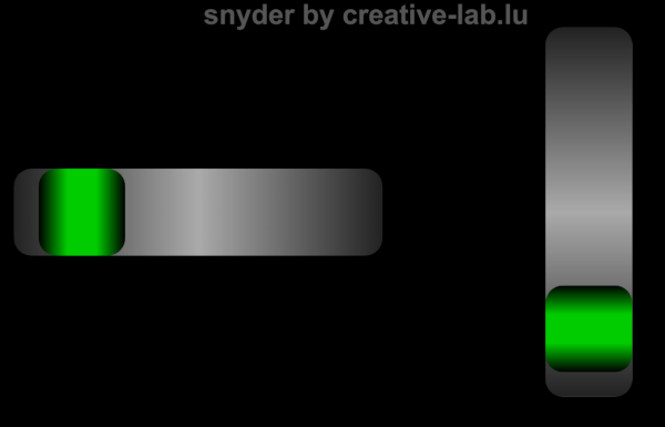
Die neue Software nutzt Websockets und reagiert wesentlich schneller. Zwei Schieberegler für Geschwindigkeit und Winkel (Steuerrad) ermöglichen eine intuitive und einfache Steuerung. Besonders gut funktioniert das mit dem Chrome Browser (Android) oder Safari Browser (iOS)!
Das Programm besteht aus 2 Dateien und kann natürlich nach Belieben angepasst werden. Der html (+css und javascript) code befindet sich in einer separaten Datei, die sich im gleichen Verzeichnis wie die .ino Datei befinden muss.
Die Arduino Bibliothek Websockets von Markus Sattler muss installiert sein (Tools > Manage libraries... > suche nach Websockets).
Here the new Arduino sketch. The new software uses Websockets an is reacting substantially faster. Two slider for speed and steering angle allow an intuitive and easy handling. Best browsers are Chrome for Android and Safari for iOS.
The html page (+ css and javascript) is contained in a separate file (in the same folder than the .ino file!). Change the files at will.
The Arduino library Websockets from Markus Sattler has to be installed (Tools > Manage libraries... > search for websockets and scroll :)).
Thanks to miharix.eu.
    /*
     *  Space Mining Rover aka snider1
     *  (ESP webserver with AP and L293D)
     *  new websockets version for both ESP *
     *  weigu.lu creative-lab.lu
     *  Version 2.1 2021-11-02
     *
     *  ESP8266: WEMOS D1 mini pro
     *  ESP32:   MH ET LIVE ESP32-MINI-KIT
     *
     *  MHET    | MHET    - WEMOS        |---| WEMOS      - MHET    | MHET
     *
     *  GND     | RST     - RST          |---| TxD        - RxD(3)  | GND
     *   NC     | SVP(36) -  A0          |---| RxD        - TxD(1)  | 27
     *  SVN(39) | 26      -  D0(16)      |---|  D1(5,SCL) -  22     | 25
     *   35     | 18      -  D5(14,SCK)  |---|  D2(4,SDA) -  21     | 32
     *   33     | 19      -  D6(12,MISO) |---|  D3(0)     -  17     | TDI(12)
     *   34     | 23      -  D7(13,MOSI) |---|  D4(2,LED) -  16     | 4
     *  TMS(14) | 5       -  D8(15,SS)   |---| GND        - GND     | 0
     *   NC     | 3V3     - 3V3          |---|  5V        -  5V     | 2
     *  SD2(9)  | TCK(13)                |---|              TD0(15) | SD1(8)
     *  CMD(11) | SD3(10)                |---|              SD0(7)  | CLK(6)
     *
     *  ESP32 framework is missing analogWrite. Option: LEDC which is PWM
     *
     *  Install the websockets library from Markus Sattler
     *  (https://github.com/Links2004/arduinoWebSockets)
     *  Tools > Manage libtraries... > search for websockets
     *
     *  Options: Relay             GPIO 33 as output
     *           Measuring voltage GPIO 33 ADC1-7
     *           Measuring current GPIO 35 ADC1-6
     */

    #ifdef ESP8266
      #include <ESP8266WiFi.h>           // ESP8266
      #include <ESP8266WebServer.h>
    #else
      #include <WiFi.h>                  // ESP32
      //#include <WiFiClient.h>
      #include <WebServer.h>
    #endif // ifdef ESP8266

    #ifndef ESP8266
      //#define RELAY            // uncomment if you use a relay (only ESP32)
      //#define MEASURE          // uncomment if you use measure current (only ESP32)
    #endif // ifndef ESP8266

    #include <WebSocketsServer.h>
    #include "html_css_js.h"

    const char *WIFI_SSID = "btsiot01";     // AP settings
    const char *WIFI_PASSWORD = "btsiot01"; // password must have min. 8 char.!!
    IPAddress IP_AP_LOCAL(192, 168, 168, 168);
    IPAddress IP_AP_GW(192, 168, 168, 1);
    IPAddress MASK_AP(255, 255, 255, 0);

    #ifdef ESP8266
      ESP8266WebServer http_server(80);    // create a web server on port 80
      WebSocketsServer ws_server(81);      // create a ws server on port 81
    #else
      WebServer http_server(80);    // create a web server on port 80
      WebSocketsServer ws_server(81);      // create a ws server on port 81
    #endif // ifdef ESP8266

    const byte SPEED_IDLE = 30;          // *2/1023 e.g. 30 gives 60 of 1023 = 6%
    const byte ANGLE_IDLE = 30;
    long switch_off_after = 1000000;      // switch rover off after milliseconds (3*60*1000)
    long last_action_time, previous_millis;

    #ifdef ESP8266
      const byte MOTOR_R1_PIN = 16;         // D0 config Wemos PINs to motor driver
      const byte MOTOR_R2_PIN = 0;          // D3
      const byte MOTOR_L1_PIN = 15;         // D8
      const byte MOTOR_L2_PIN = 13;         // D7
    #else
    const byte MOTOR_R1_PIN = 26; // D0 config pinss to motor driver
    const byte MOTOR_R2_PIN = 17; // D3
    const byte MOTOR_L1_PIN = 5;  // D8
    const byte MOTOR_L2_PIN = 23; // D7
    const byte MOTOR_R1_PWM = 1;  // pwm channel
    const byte MOTOR_R2_PWM = 2;
    const byte MOTOR_L1_PWM = 3;
    const byte MOTOR_L2_PWM = 4;
    #endif // ifdef ESP8266

    #ifdef RELAY
      const byte RELAY_PIN = 33; // GPIO
    #endif // ifdef RELAY
    #ifdef MEASURE
      const byte VOLT_PIN = 35; // Analog input to measure voltage
      const byte CURR_PIN = 34;  // Analog input to measure current
      int adc_voltage, adc_current;
      double voltage, current;
    #endif // ifdef MEASURE

    short speed, angle;

    /******** SETUP ***************************************************************/

    void setup() {
      Serial.begin(115200);
      delay(500);
      Serial.println("Serial ok");
      delay(500);
      #ifdef RELAY
        pinMode(RELAY_PIN,OUTPUT);
        delay(100);
        digitalWrite(RELAY_PIN,HIGH);        // hold the relay
        Serial.println("Relay on");
        delay(500);
      #endif // ifdef RELAY
      init_LED();
      LED_on();
      init_motors();                     // init motor pins and
      action(0,0,0,0);                   // stop the motors
      init_wifi_ap();                    // init wifi access point
      init_ws_server();                  // init websocket_server server
      init_http_server();                // init a http server
      #ifdef MEASURE
        previous_millis = millis();
      #endif // #ifdef MEASURE
    }
    /***** MAINLOOP ***************************************************************/

    void loop() {
      #ifdef RELAY
        if (millis()-last_action_time > switch_off_after) {
          digitalWrite(RELAY_PIN,LOW);     // switch off
        }
      #endif // ifdef RELAY
      #ifdef MEASURE
        adc_voltage = analogRead(VOLT_PIN);
        adc_current = analogRead(CURR_PIN);
        voltage = adc_voltage*7.0/4096;
        current = adc_current*5000/(4096*19); // g = 19 I = (adc_current/19)/R = *0,2Ohm
        if ((millis()-previous_millis) > 2000) {
          Serial.print("voltage = ");
          Serial.print(voltage);
          Serial.print(" V\t");
          Serial.print("current = ");
          Serial.print(current);
          Serial.println(" mA");
          previous_millis = millis();
        }
      #endif // ifdef MEASURE
      ws_server.loop();                  // check for websocket_server events
      http_server.handleClient();        // wait for http requests
    }
    /***** Init functions *********************************************************/

    // build in LED on
    void LED_on() {
      digitalWrite(LED_BUILTIN,LOW);     // LED on (negative logic)
    }

    // build in LED off
    void LED_off() {
      digitalWrite(LED_BUILTIN,HIGH);    // LED off (negative logic)
    }

    // initialise the build in LED and switch it on
    void init_LED() {
      pinMode(LED_BUILTIN,OUTPUT);
      LED_on();
    }

    // initialise the motor pins as output
    void init_motors() {
      #ifdef ESP8266
        analogWriteRange(1023);             // needed for ESP8266 core beginning with 3.0
        pinMode(MOTOR_R1_PIN, OUTPUT);      // 4 pins to motor driver as output
        pinMode(MOTOR_R2_PIN, OUTPUT);
        pinMode(MOTOR_L1_PIN, OUTPUT);
        pinMode(MOTOR_L2_PIN, OUTPUT);
      #else
        ledcAttachPin(MOTOR_R1_PIN, MOTOR_R1_PWM); // assign output pins to PWM channels
        ledcAttachPin(MOTOR_R2_PIN, MOTOR_R2_PWM);
        ledcAttachPin(MOTOR_L1_PIN, MOTOR_L1_PWM);
        ledcAttachPin(MOTOR_L2_PIN, MOTOR_L2_PWM);
        ledcSetup(MOTOR_R1_PWM, 1000, 10); // 1 kHz PWM, 10-bit resolution
        ledcSetup(MOTOR_R2_PWM, 1000, 10);
        ledcSetup(MOTOR_L1_PWM, 1000, 10);
        ledcSetup(MOTOR_L2_PWM, 1000, 10);
      #endif // ifdef ESP8266
    }

    // initialize wifi ap
    void init_wifi_ap() {
      WiFi.softAPConfig(IP_AP_LOCAL, IP_AP_GW, MASK_AP);
      WiFi.softAP(WIFI_SSID, WIFI_PASSWORD);             // start the access point
      IPAddress myIP = WiFi.softAPIP();
      Serial.print("Access Point ");
      Serial.println(WIFI_SSID);
      Serial.print("AP IP address: ");
      Serial.println(myIP);
    }

    // init websocket_server server
    void init_ws_server() {
      ws_server.begin();                 // start the ws server
      ws_server.onEvent(ws_server_event);// if ws message, websocket_server_event()
    }

    // init a http server and handle http requests: http://192.168.168.168/
    void init_http_server() {
      http_server.onNotFound(handle_not_found);
      http_server.on("/", handle_root);  // (don't forget the "/")
      http_server.begin();               // start the HTTP server
      http_server.setContentLength(html_css_js.length()); // needed to avoid net:err
    }
    /***** SERVER handlers ********************************************************/

    // if the requested page doesn't exist, return a 404 not found error
    void handle_not_found() {
      http_server.send(404, "text/plain", "404: Not Found");
    }

    // handle root (deliver webpage)
    void handle_root() {
      LED_on();
      http_server.send(200,"text/html",html_css_js); // HTTP response code 200
      LED_off();
    }

    // do this when a websocket_server message is received
    void ws_server_event(byte num, WStype_t type, byte * payload, size_t lenght) {
      switch (type) {
        case WStype_DISCONNECTED:        // if the websocket_server is disconnected
          break;
        case WStype_CONNECTED: {         // if new websocket_server con. established
            //IPAddress ip = ws_server.remoteIP(num);
            ws_server.remoteIP(num);
          }
          break;
        case WStype_TEXT:                // if new text data is received
          if (payload[0] == '#') {       // we get slider data
            unsigned long pl = (unsigned long) strtol((const char *) &payload[1],
                              NULL, 16);// string data to number
            int speed = pl & 0x3FF;      // retrieve both slider data (0-1023)
            int angle= (pl >> 12) & 0x3FF; // G: bits 12-24
            Serial.print(speed);
            Serial.print('\t');
            Serial.println(angle);
            if ((angle <= (512 + ANGLE_IDLE)) &&
                (angle >= (512 - ANGLE_IDLE))) {     // straight
              if (speed > (512 + SPEED_IDLE)) {
                action(speed,0,speed,0);             // straight forward
              }
              else if (speed < (512 - SPEED_IDLE)) {
                action(speed,1023,speed,1023);       // straight backwards
              }
              else {
                action(0,0,0,0);                     // stop
              }
            }
            else if (angle < (512 - ANGLE_IDLE)) {   // turn right
              angle = -((512 + ANGLE_IDLE)-angle);
              if (speed > (512 + SPEED_IDLE)) {      // right forward
                action(speed,0,speed+angle,0);
              }
              else if (speed < (512 - SPEED_IDLE)) {
                action(speed,1023,speed-angle,1023); // right backwards
              }
              else {
                action(0,0,0,0);
              }
            }
            else {                                   // turn left
              angle = (512 - ANGLE_IDLE)-angle;
              if (speed > (512 + SPEED_IDLE)) {      // left forward
                action(speed+angle,0,speed,0);
              }
              else if (speed < (512 - SPEED_IDLE)) { // left backwards
                action(speed-angle,1023,speed,1023);
              }
              else {
                action(0,0,0,0);
              }
            }
          }
          break;
      }
    }
    /***** HELPER functions********************************************************/

    void action(int MOTOR_R1, int MOTOR_R2, int MOTOR_L1, int MOTOR_L2) {
      LED_on();
      #ifdef ESP8266
        analogWrite(MOTOR_R1_PIN, MOTOR_R1);
        analogWrite(MOTOR_R2_PIN, MOTOR_R2);
        analogWrite(MOTOR_L1_PIN, MOTOR_L1);
        analogWrite(MOTOR_L2_PIN, MOTOR_L2);
      #else
        ledcWrite(MOTOR_R1_PWM, MOTOR_R1);
        ledcWrite(MOTOR_R2_PWM, MOTOR_R2);
        ledcWrite(MOTOR_L1_PWM, MOTOR_L1);
        ledcWrite(MOTOR_L2_PWM, MOTOR_L2);
      #endif // ifdef ESP8266
      LED_off();
      last_action_time = millis();
    }
Schaltplan / Circuit
Alte Software / Older Software without websockets
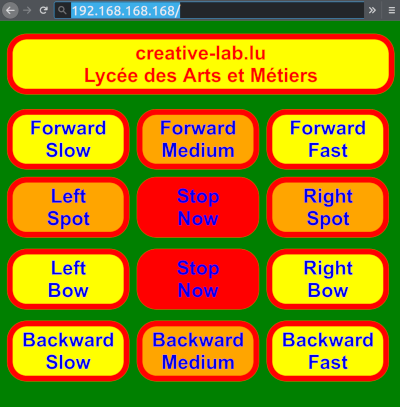
Hier das Arduino Programm , das natürlich nach Belieben angepasst werden soll.
Here the basic Arduino sketch. Change it at will.
/*
* Space Mining Rover aka snider1
* (wemos webserver with AP and L293D)
* creative-lab.lu
*/
#include <ESP8266WiFi.h>
#include <ESP8266WebServer.h>
const char *ssid = "creative23"; // AP settings
const char *password = "creative23"; // password must have more than 7 characters!!
IPAddress IP_AP(192, 168, 168, 168);
IPAddress MASK_AP(255, 255, 255, 0);
ESP8266WebServer server(80); // create object with name "server" port 80
const int slow = 500; // speed (500 to get min 2,5V)
const int medium = 750;
const int fast = 1023; // max. 1023)
const int bowdiff = 150; // if bigger, lesser radius
const byte LED = 2; // D4
const byte MotorR1_pin = 16; // D0 config Wemos pins to motor driver
const byte MotorR2_pin = 0; // D3
const byte MotorL1_pin = 15; // D8
const byte MotorL2_pin = 13; // D7
// here comes the html and css magic
String myhtml = R"=====(
<!DOCTYPE html>
<html>
<head>
<title>creative-lab.lu</title>
</head>
<style>
body {font-family: Arial, Verdana, sans-serif;
font-size: 12px;
color: red;
background-color: green;}
div {margin: 0.2em auto;
width: 100%;
clear: both;}
p {margin: 0.2em;
padding: 0.1em;
border-radius: 1em;
background-color: yellow;
border: 0.3em red solid;
font-size: 4em;
font-weight: bolder;
text-align: center;}
p.center {margin: 0.2em auto;
width: 27%;
clear: both;}
p.lam {clear: both;}
p.main {background-color: orange;
width: 27%;
float: left;}
p.side {width: 27%;
float: left;}
p.stop {background-color: red;
width: 27%;
float: left;
margin-bottom: 0.4em;}
a {display: block;
text-decoration: none;}
</style>
<body>
<br><p class="lam">creative-lab.lu
<br/>Lycée des Arts et Métiers</p><br>
<div>
<p class="side"><a href=/forwards>Forward<br/>Slow</a></p>
<p class="main"><a href=/forwardm>Forward<br/>Medium</a></p>
<p class="side"><a href=/forwardf>Forward<br/>Fast</a></p>
</div><div>
<p class="main"><a href=/lefts>Left<br/>Spot</a></p>
<p class="stop"><a href=/halt>Stop<br/>Now</a></p>
<p class="main"><a href=/rights>Right<br/>Spot</a></p>
</div><div>
<p class="side"><a href=/leftb>Left<br/>Bow</a></p>
<p class="stop"><a href=/halt>Stop<br/>Now</a></p>
<p class="side"><a href=/rightb>Right<br/>Bow</a></p>
</div><div>
<p class="side"><a href=/backwards>Backward<br/>Slow</a></p>
<p class="main"><a href=/backwardm>Backward<br/>Medium</a></p>
<p class="side"><a href=/backwardf>Backward<br/>Fast</a></p>
</div>
</body>
</html>
)=====";
void setup() {
analogWriteRange(1023); // needed for ESP8266 core beginning with 3.0
pinMode(MotorR1_pin, OUTPUT); // 4 pins to motor driver as output
pinMode(MotorR2_pin, OUTPUT);
pinMode(MotorL1_pin, OUTPUT);
pinMode(MotorL2_pin, OUTPUT);
pinMode(D4, OUTPUT); // blue LED Pin (D4) as output
digitalWrite(D4, LOW); // LED on (negative logic)
action(0,0,0,0); // stop the motors
/*digitalWrite(Motor_R_PWM_1, LOW);
digitalWrite(Motor_R_PWM_2, LOW);
digitalWrite(Motor_L_PWM_1, LOW);
digitalWrite(Motor_L_PWM_2, LOW);*/
WiFi.softAPConfig(IP_AP, IP_AP, MASK_AP);
WiFi.softAP(ssid, password);
// handle http requests; root must be called! type: http://192.168.168.168/
server.on("/", handleRoot); // (don't forget the "/")
server.on("/forwards", forwards);
server.on("/forwardm", forwardm);
server.on("/forwardf", forwardf);
server.on("/lefts", lefts);
server.on("/rights", rights);
server.on("/halt", halt);
server.on("/leftb", leftb);
server.on("/rightb", rightb);
server.on("/backwards", backwards);
server.on("/backwardm", backwardm);
server.on("/backwardf", backwardf);
server.begin();
server.setContentLength(myhtml.length()); // if not given we get
} // net:err_content_length_mismatch
void loop() {
server.handleClient(); // wait for http requests
}
void handleRoot() {
digitalWrite(LED, LOW);
server.send(200,"text/html",myhtml); // HTTP response code 200 (alt. 404)
digitalWrite(LED, HIGH);
}
void forwards() { action(slow,0,slow,0); }
void forwardm() { action(medium,0,medium,0); }
void forwardf() { action(fast,0,fast,0); }
void lefts() { action(slow,0,1023-slow,1023); }
void rights() { action(1023-slow,1023,slow,0); }
void halt() { action(0,0,0,0); }
void rightb() { action(slow,0,slow+bowdiff,0); }
void leftb() { action(slow + bowdiff,0,slow,0); }
void backwards() { action(1023-slow,1023,1023-slow,1023); }
void backwardm() { action(1023-medium,1023,1023-medium,1023); }
void backwardf() { action(1023-fast,1023,1023-fast,1023); }
void action(int MotorR1, int MotorR2, int MotorL1, int MotorL2) {
digitalWrite(LED, LOW);
analogWrite(MotorR1_pin, MotorR1);
analogWrite(MotorR2_pin, MotorR2);
analogWrite(MotorL1_pin, MotorL1);
analogWrite(MotorL2_pin, MotorL2);
server.send(200, "text/html",myhtml);
digitalWrite(LED, HIGH);
}
Downloads
Interesting links:
- The rover using an ESP32 and further options: http://weigu.lu/tutorials/electronics/01_rover/index.html
