Microcontroller projects
last updated: 2024-05-03
Growing station: Control the LED grow light and a fan
Quick links
Intro
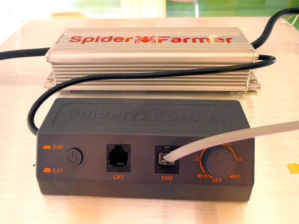
It's spring and it's time to grow my little organic plants for the garden. This will happen indoors, but this year there is not much light from outside, so I decided to buy an LED Grow Light SF2000Pro from Spider Farmer. This panel is efficient and can be controlled from outside. For the beginning I added an environmental sensor (Bosch BME680) to measure temperature, humidity, (pressure) and gas, and three light sensors TSL2561 to measure the light in lux and control the grow light.
After this I added a fan to avoid the temperature to rise to high under the LED.
BOM and circuit
- 1 SF2000Pro from Spider Farmer
- 1 ESP32 Olimex POE board
- 1 BME680 environmental sensor
- 3 TSL2561 light sensors
- 1 4N25 optocoupler
- 2 resistor 10 kΩ
- 1 resistor 180 Ω
- 1 resistor 100 Ω
- 1 IR LED 5 mm
- 1 fan EsayAcc KW-MF03BJ
The circuit is not complicated. A little research and hacking showed, that the RJ12 connector uses 4 pins connected to two cables (black and red) connected to the dimmable power supply.
These power supplies have normally a 3-in-1 dimming feature (0-10V, 10V PWM, 0-100kOhm). It seems that this control input generates a constant current of about 0.1 mA (internal Pull-Up with high resistance to 10 V) to measure the resistance. So a simple transistor can be used to change the input voltage. I use an optocoupler to do so.
For the ESP32 I chose an Olimex POE board. I will use the Ethernet connector with POE, but for the moment I use WiFi because I have no Ethernet socket in the room.
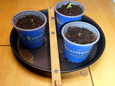
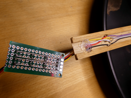
The 4 sensors are connected in parallel to the I2C bus and fixed on a wooden stick. I used a prototyping PCB for the circuit.
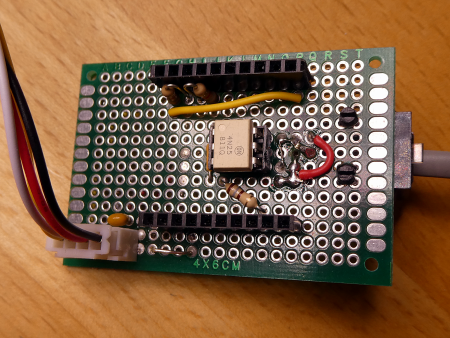
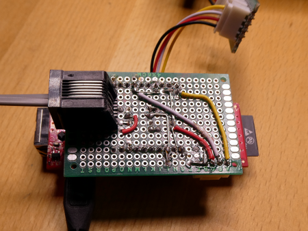
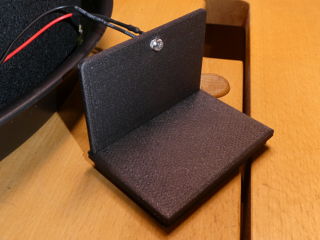
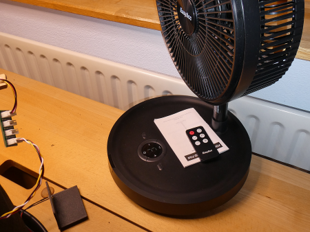
The fan from EasyAcc runs on battery and can be adjusted in height. I use the program natural wind and oscillations (30°). First I wanted to hack the electronics. After opening the fan, the effort involved seemed too high, so I decided to control it via the infrared interface (remote control). I connected an IR LED to the board for this purpose.
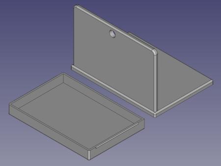
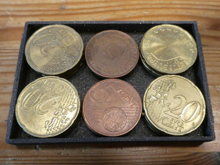
To mount the IR LED I printed an 3D box filled with money :) by using my recent freecad macro.
Software
The software communicates per MQTT over WiFi. It uses my ESPToolbox library for WiFi and UDP logging functions and to get the time. To avoid version problems the lib is included in the sketch folder. Programming is done over OTA.
Other libraries needed:
- PubSubClient by Nick O'Leary
- ArduinoJson by Benoit Blanchon
- Adafruit TSL2561
- Adafruit BME280 or
- Adafruit BME680
- IRremoteESP8266 by David Conran
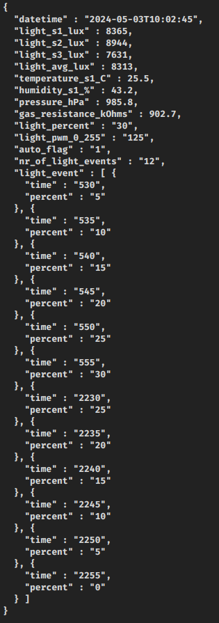
The software is a first draft and for the moment we get only the data topic:
String MQTT_TOPIC_OUT = "weigu/garden/watering/data";
and the following is seen on the data channel:
All relevant data you must or can change are in a config (config.h) file, also contained in the main folder. You can also place this file in the sketchbook/library folder named Secrets and rename it to your needs (e.g. secrets.h).
In the main file (.ino) you can activate or deactivate features by commenting or uncommenting some lines. Here you must activate USE_SECRETS:
/*!!!!!!       Make your changes in config.h (or secrets_xxx.h)      !!!!!!*/

/*------ Comment or uncomment the following line suiting your needs -------*/
#define USE_SECRETS
#define OTA               // if Over The Air update needed (security risk!)
#define STATIC            // if static IP needed (no DHCP)
#define TSL2561           // 3 TSL2561 light sensors
//#define BME280_I2C      // 1 BME280 temp., hum., press. sensor
#define BME680_I2C        // 1 BME680 environmental sensor
#define FAN               // EasyAcc foldable stand fan KW-MF03BJ with IR commands
In the config.h file, you must change the WiFi parameter and the MQTT server address. In the automated light_events array we define the start times and brightness of the light. In setup we have the function set_pwm_light_lux(light_lux) that alters the brighness by measering the sensor light data (average) and adjusts the light in percent. If we want a max e.g. of 7500 lux this function reduces the max percentage to e.g. 30 % and reduces also the other percentages in the array. You can comment this function if not needed.
Other things we perhaps want to change are the publishing interval PUBLISH_TIME or the MQTT topics.
Here is the content of the config.h file:
/****** WiFi SSID and PASSWORD ******/
const char *MY_WIFI_SSID = "your_ssid";
const char *MY_WIFI_PASSWORD = "your_password";

/****** WiFi and network settings ******/
// UDP logging settings if enabled in setup(); Port used for UDP logging
const word UDP_LOG_PORT = 6464;
// IP address of the computer receiving UDP log messages
const byte UDP_LOG_PC_IP_BYTES[4] = {192, 168, 178, 100};
// optional (access with UDP_logger.local)
const char *NET_MDNSNAME = "growing_station";
// optional hostname
const char *NET_HOSTNAME = "growing_station";
// only if you use a static address (uncomment //#define STATIC in ino file)
const byte NET_LOCAL_IP_BYTES[4] = {192, 168, 178, 155};
const byte NET_GATEWAY_BYTES[4] = {192, 168, 178, 1};
const byte NET_MASK_BYTES[4] = {255,255,255,0};
const byte NET_DNS_BYTES[4] = {8,8,8,8}; //  second dns (first = gateway), 8.8.8.8 = google
// only if you use OTA (uncomment //#define OTA in ino file)
const char *MY_OTA_NAME = "growing_station"; // optional (access with esp_with_ota.local)
// Linux Create Hasgh with: echo -n 'P@ssword1' | md5sum
const char *MY_OTA_PASS_HASH = "myHash";     // Hash for password

/****** MQTT settings ******/
const char *MQTT_SERVER = "192.168.178.222";
const long PUBLISH_TIME = 10000; //Publishes every in milliseconds
const int MQTT_MAXIMUM_PACKET_SIZE = 1024; // look in setup()
const char *MQTT_CLIENT_ID = "growing_station_15287952425"; // this must be unique!!!
String MQTT_TOPIC_OUT = "weigu/growing_station/data";
String MQTT_TOPIC_IN = "weigu/growing_station/command";
const short MY_MQTT_PORT = 1883; // or 8883
// only if you use MQTTPASSWORD (uncomment //#define MQTTPASSWORD in ino file)
const char *MY_MQTT_USER = "me";
const char *MY_MQTT_PASS = "meagain";

/****** BME sensors ******/
bool flag_bme280_available = false;
bool flag_bme680_available = false;

/****** Fan IR control ******/
const byte PIN_IR_LED = 5;

/****** Light control ******/
bool flag_TSL2561_1_available = false;
bool flag_TSL2561_2_available = false;
bool flag_TSL2561_3_available = false;

const byte LED_PWM_PIN = 3;
const byte LED_PWM_CHANNEL = 0;      // channels 0-15
const unsigned int PWM_FREQ = 1000;  // freq limits depend on resolution
const byte PWM_RES = 8;              // resolution 1-16 bits
byte light_percent = 0;
byte light_pwm = 0;
unsigned int light_lux = 7500;

struct pwm {
  byte light_percent;
  byte light_pwm;
};

pwm light_pwm_table[] = {
  {  0, 255},
  {  5, 195},
  { 10, 178},
  { 15, 162},
  { 20, 147},
  { 25, 136},
  { 30, 125},
  { 35, 114},
  { 40, 104},
  { 45,  94},
  { 50,  83},
  { 55,  73},
  { 60,  62},
  { 65,  51},
  { 70,  41},
  { 75,  30},
  { 80,  20},
  { 85,   8},
  { 90,   2},
  { 95,   1},
  {100,   0}
};

/******* Automated light control *******/
bool auto_flag = 1;

struct le {
  unsigned int start_time;
  unsigned int light_percent;
};
// light events should be an even number, last event light percent = 0
le light_events[] = {
  {530,10},
  {535,20},
  {540,30},
  {545,40},
  {550,50},
  {555,60},
  {2230,50},
  {2235,40},
  {2240,30},
  {2245,20},
  {2250,10},
  {2255,0}
};

byte nr_of_light_events = sizeof(light_events)/sizeof(light_events[0]);
The fan is activated every 2 hours for 1 hour (timer) with the following function:
void handle_fan() {
  if ((Tb.t.hour >= 6) && (Tb.t.hour <= 22) && (Tb.t.hour%2 == 0)
     && (Tb.t.minute == 0) && (Tb.t.second == 0)) {
    fan_1_hour_natural_oscillate();
    Tb.log_ln("IR control for fan sent!");
  }
}

void fan_1_hour_natural_oscillate() {
  fan_send_command_on_off(); // on
  delay(100);
  fan_send_command_timing(); // 1h
  delay(100);
  fan_send_command_plus();
  delay(100);
  fan_send_command_oscillate();
  delay(100);
  fan_send_command_oscillate(); // reduce to 30 degree
  delay(100);
  fan_send_command_natural_wind();
}
The code is on Github.
Openhab
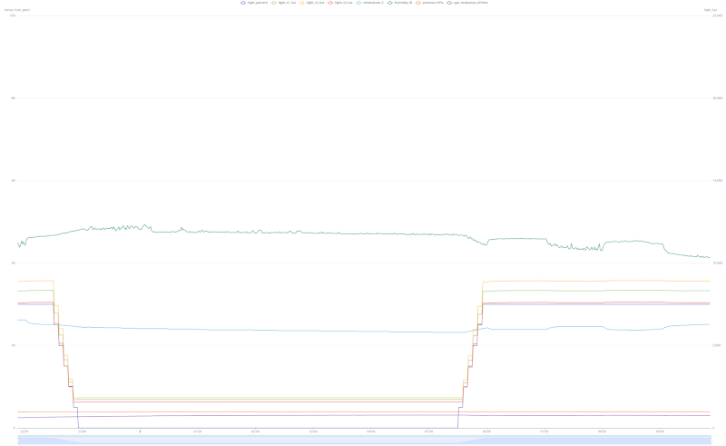
I often use Openhab to visualise my data. The yaml files are also on github.
Downloads
