Microcontroller projects
Direct Digital Synthesis DDS with microcontroller
last updated: 2021-11-01
Quick links
- Introduction
- Using a wavetable (lookup table)
- So why DDS?
- DDS with the microcontroller
- Downloads
- Interesting links
Introduction
In Direct Digital Synthesis, a periodic, band-limited analogue signal (e.g. a sine wave) is generated from a time-varying digital signal with the help of a D/A converter or a PWM.
The great advantage of the DDS method is the very fine frequency resolution. Further advantages are the fast switching between frequencies, the large achievable bandwidth and high frequency stability.
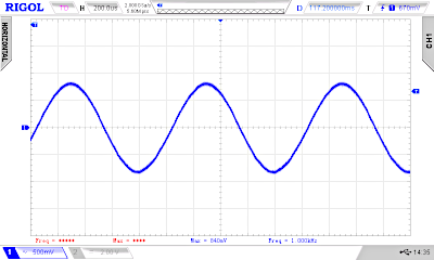
The widespread use of ICs that realise the complete hardware of a synthesiser according to the DDS method has contributed significantly to the success of the method.
We want to understand the method and use it in microcontroller.
Using a wavetable (lookup table)
Calculating e.g. a sine wave with an amplitude resolution of 8 bits (u=255*sin(α)) with a simple microcontroller like the Atmega328p from the Arduino Uno would take far too long. It is easier to store the amplitude values of an oscillation in a table (called wavetable or lookup table) and then access them. However, the frequency is then determined by the access speed of the program.
Lookup tables can be created online with a sine look-up table generator e.g. https://www.daycounter.com/Calculators/Sine-Generator-Calculator.phtml). Here a table for a sine wave with 256 values (8 bit pointer) and with an amplitude of 1 byte (8 bit, 0-255, 0x00-0xFF)
    // sine_table_256_values_8_bit.h

    const uint16_t SINE_256V_8B [256] {
      0x80,0x83,0x86,0x89,0x8c,0x8f,0x92,0x95,
      0x98,0x9b,0x9e,0xa2,0xa5,0xa7,0xaa,0xad,
      0xb0,0xb3,0xb6,0xb9,0xbc,0xbe,0xc1,0xc4,
      0xc6,0xc9,0xcb,0xce,0xd0,0xd3,0xd5,0xd7,
      0xda,0xdc,0xde,0xe0,0xe2,0xe4,0xe6,0xe8,
      0xea,0xeb,0xed,0xee,0xf0,0xf1,0xf3,0xf4,
      0xf5,0xf6,0xf8,0xf9,0xfa,0xfa,0xfb,0xfc,
      0xfd,0xfd,0xfe,0xfe,0xfe,0xff,0xff,0xff,
      0xff,0xff,0xff,0xff,0xfe,0xfe,0xfe,0xfd,
      0xfd,0xfc,0xfb,0xfa,0xfa,0xf9,0xf8,0xf6,
      0xf5,0xf4,0xf3,0xf1,0xf0,0xee,0xed,0xeb,
      0xea,0xe8,0xe6,0xe4,0xe2,0xe0,0xde,0xdc,
      0xda,0xd7,0xd5,0xd3,0xd0,0xce,0xcb,0xc9,
      0xc6,0xc4,0xc1,0xbe,0xbc,0xb9,0xb6,0xb3,
      0xb0,0xad,0xaa,0xa7,0xa5,0xa2,0x9e,0x9b,
      0x98,0x95,0x92,0x8f,0x8c,0x89,0x86,0x83,
      0x80,0x7c,0x79,0x76,0x73,0x70,0x6d,0x6a,
      0x67,0x64,0x61,0x5d,0x5a,0x58,0x55,0x52,
      0x4f,0x4c,0x49,0x46,0x43,0x41,0x3e,0x3b,
      0x39,0x36,0x34,0x31,0x2f,0x2c,0x2a,0x28,
      0x25,0x23,0x21,0x1f,0x1d,0x1b,0x19,0x17,
      0x15,0x14,0x12,0x11,0x0f,0x0e,0x0c,0x0b,
      0x0a,0x09,0x07,0x06,0x05,0x05,0x04,0x03,
      0x02,0x02,0x01,0x01,0x01,0x00,0x00,0x00,
      0x00,0x00,0x00,0x00,0x01,0x01,0x01,0x02,
      0x02,0x03,0x04,0x05,0x05,0x06,0x07,0x09,
      0x0a,0x0b,0x0c,0x0e,0x0f,0x11,0x12,0x14,
      0x15,0x17,0x19,0x1b,0x1d,0x1f,0x21,0x23,
      0x25,0x28,0x2a,0x2c,0x2f,0x31,0x34,0x36,
      0x39,0x3b,0x3e,0x41,0x43,0x46,0x49,0x4c,
      0x4f,0x52,0x55,0x58,0x5a,0x5d,0x61,0x64,
      0x67,0x6a,0x6d,0x70,0x73,0x76,0x79,0x7c
    };
We store this table in a separate header file called sine_table_256_8bit.h that is stored in the same folder than the Arduino sketch.
Doing it with Arduino Uno
OK let's test it with an Arduino Uno board. Do do this we need to look at the data sheet of the ATmega328p controller, do tweak the timer register.
PWM output
We want to use a PWM output instead of a DAC to simplify the wiring (1 output instead of 8). The Arduino PWM frequency is here too low (490 Hz) to be useful (analogWrite()). We want the maximum frequency, that we get in fast PWM mode without pre-scaler.fPWM = 16 MHz / 256 = 62.5 kHz.
To use a PWM output we need a low-pass filter to separate the PWM frequency from our analogue signal frequency. For more infos look here: http://weigu.lu/tutorials/electronics/06_capacitor_inductor/index.html#link_1
The filter frequency can be calculated if we know the values from the resistor and the capacitor.
We choose a cut-off frequency of one tenth of the PWM frequency (6 kHz), and a capacitor of 100 nF. By changing the formula we can calculate the resistor. We get a value of about 270 Ω. This gives us the following circuit:
We can use a high impedance headphone to listen to the sound.
Software
The controller has 3 Timer. Timer0 is already taken by the Arduino code (for e.g. delay()). We will use the 8-bit Timer2 for the PWM. The output pin is pin D11 and the register to output the values is OCR2A.
We use 16bit Timer1 to generate an CTC interrupt with 100 kHz. To do so we need 160 counter steps (0-159) so OCR1A = 159.fISR = 16 MHz / 160 = 100 kHz.
    /* wavetable_arduino_uno_256v_8b.ino
     * weigu.lu
     * PWM output on pin 11 connected to low-pass 100nF, 270 Ohm
     */

    #include "sine_table_256_values_8_bit.h"

    const uint8_t PIN_PWM_TIMER2A = 11; // PWM output on Uno
    const uint8_t TABLE_POINTER_INCREMENT = 10; // every value
    uint8_t table_pointer = 0;

    /* Timer1 interrupt gets table values and outputs them */
    ISR(TIMER1_COMPA_vect){
      OCR2A = SINE_256V_8B[table_pointer];
      table_pointer = table_pointer + TABLE_POINTER_INCREMENT;
    }

    void setup() {
      pinMode(PIN_PWM_TIMER2A, OUTPUT);
      cli();         // stop interrupts
      /* Set Timer2 register to FastPWM */
      TCCR2A = 0xA3;
      TCCR2B = 0x01; // no prescaling (f_PWM = 16MHz/256 = 62,5kHz)
      /* Set Timer1 for Timer interrupt */
      TCCR1A = 0;
      TCCR1B = 0x09; // turn on CTC mode no prescaler
      OCR1A = 159;   // f = 16MHz / (OCCR1A - 1) = 100kHz
      TIMSK1 = 0x02; // enable timer compare interrupt
      sei();         //allow interrupts
    }

    void loop() { // everything in the ISR
    }
Changing the frequency
With a sine table like this (256 values) and a timer interrupt with 100 kHz to get the data, we get a maximum frequency of: 100 kHz / 256 = 390.625 Hz. Changing the frequency is only possible by changing the timer interrupt frequency.
With a trick, we can get higher frequencies at our output. If only every second table value is used, the frequency doubles. With every third value, the frequency triples and so on. Here an example with a table containing 16 values:
Let's try it by changing the TABLE_POINTER_INCREMENT = 1 constant to 2 and then to 10. Here the oscilloscope screens (without headphone):
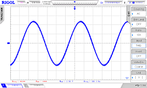
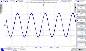
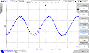
We see that the frequency goes up from 391 Hz to 778 Hz and to 3.9 kHz.
In theory at least 2 values must be transmitted per period (Nyquist rate). In praxis we need much more than 2 points, so the maximum frequency is therefore also limited. We could also get better results with a steeper low-pass filter.
So why DDS?
We get only multiples of the base frequency and this frequency can also only be changed very roughly by changing the interrupt pre-scaler. So this solution is not really satisfying.
Not using an interrupt and working with delay() is not a solution either because the strict timing we need for the PWM is not given.
With the help of the DDS, the named disadvantages can be avoided. With DDS we get a very fine frequency resolution under 1 Hz.
DDS with the microcontroller
Phase accumulator (phase register)
Instead of a simple binary counter (table pointer) that calls the table values a in sequence, we use a big register called phase accumulator or phase register with N bits. This register is much larger than would be necessary to address the table. Usually, registers with 4 or 6 bytes (N = 32 or 48 bits) are used. Only the upper P bits (for example 8 bits for a table with 256 values) of the phase accumulator are then used to address the table. The register with P bits is called the address pointer.
For the number of bits used for our amplitude (resolution) we use the character B. It defines the number of output pins for our DAC or the length of our PWM register (8 bit with Timer2).
Block diagram
This gives us the following block diagram for DDS:
Output frequency
The output frequency fout is given by the following formula:
fCLK is the frequency with which the values are output to a D/A converter (DAC) or with a PWM. So fCLK will correspond e.g. to the frequency of a timer interrupt.
The formula shows that the higher the frequency fCLK, the higher the frequencies that can be generated.
However, if the frequency of a interrupt is too high for the microcontroller, the main programme will run out of time. In the AVR synthesizer meeblib (meeblip.com), for example, a frequency of 36.36 kHz was chosen. This leaves about 440 clock cycles for processing the data (ISR + main programme) with the 16 MHz crystal used.
The higher the frequency fout to be generated becomes in comparison to fCLK, the more "imperfections" of the DDS principle become noticeable through jitter, noise and spurious waves in the spectrum.
Example: Phase accumulator with 4 bytes
For this example we reduce the register to 12 bit: N = 12 bit → phase accumulator and offset have 12 bit width.
Only the upper 4 bits are used for the address pointer P = 4 bit. The table has 16 values with an amplitude of 8 bit B = 8 (0-255).
    const uint8_t SINE_16V_8B[16] {
      0x80,0xb0,0xda,0xf5,0xff,0xf5,0xda,0xb0,
      0x80,0x4f,0x25,0xa,0x00,0x0a,0x25,0x4f
    };

    /* in decimal:
      128,176,218,245,255,245,218,176,
      128,79,37,10,0,10,37,79*/
The phase register is increased by a fixed phase offset (phase increment), here called offset. This phase offset register has the same size as the phase register. When in the addition of phase accumulator and offset an overflow occurs, the overflow is ignored (modulo 2N).
Now, not only integer multiples of the frequency are possible, but also intermediate values (the effect is the same as if one were to work with decimal places, e.g. take every 1.3rd value).
phase accu (pointer) |
offset |
||
|---|---|---|---|
000000000000 (0000 = 0) |
+ |
001000110000 | |
= |
001000110000 (0010 = 2) |
+ |
001000110000 |
= |
010001100000 (0100 = 4) |
+ |
001000110000 |
= |
011010010000 (0110 = 6) |
+ |
001000110000 |
= |
100011000000 (1000 = 8) |
+ |
001000110000 |
= |
101011110000 (1010 = 10) |
+ |
001000110000 |
= |
110100100000 (1101 = 13) |
+ |
001000110000 |
= |
111101010000 (1111 = 15) |
+ |
001000110000 |
= |
000110000000 (0001 = 1) |
+ |
001000110000 |
= |
001110110000 (0011 = 3) |
+ |
001000110000 |
= |
010111100000 (0101 = 5) |
+ |
001000110000 |
= |
100000010000 (1000 = 8) |
+ |
.... |
We see that about 6 values per period are used, but the values change all the time.
Let's go back to our example: N = 12 bit. We assume a clock frequency fCLK of 36363 Hz. The offset is 0b001000110000 = 56010.
With this values we get a frequency of 4.97 kHz. The resolution says that by changing the offset by 1, the frequency changes by 8.878 Hz. So if the offset is increased by 1 (561), the frequency increases to 4980.38 Hz.
The smallest frequency (basic frequency of the table, all 16 values) without DDS results with fout_bf = 2272.7 Hz. The frequency was therefore increased with this offset by the factor fout/fout_bf = 4971.5/2272.7 = 2.187.
By the way, the basic frequency is reached with the offset 0b0001000000 = 256. Smaller frequencies than the basic frequency are also possible with the DDS down to offset = 1 (fout = 8.8 Hz).
Arduino Uno
We used a small table only to better understand DSS. For fun, here is the code:
    /* dds_arduino_uno_16v_8b.ino
     * weigu.lu
     * N = 12, P = 4, B = 8, res = 8.8777Hz
     * PWM output on pin 11 connected to low-pass
     * fout = fCLK/offset*2^N, fout = 8,877Hz/offset
     */

    const uint8_t SINE_16V_8B[16] {
      0x80,0xb0,0xda,0xf5,0xff,0xf5,0xda,0xb0,
      0x80,0x4f,0x25,0xa,0x00,0x0a,0x25,0x4f
    };

    const uint8_t PIN_PWM_TIMER2A = 11; // PWM output on Uno
    uint16_t phase_offset = 560;
    uint16_t phase_accumulator = 0x0000;
    uint8_t  address_pointer = 0x00;

    /* Timer1 interrupt calculates the pointer, gets the value
      for the PWM from the table and outputs it */
    ISR(TIMER1_COMPA_vect){
      phase_accumulator = (phase_accumulator + phase_offset) % 4096;
      address_pointer = phase_accumulator >> 8; // 1 byte
      OCR2A = SINE_16V_8B[address_pointer];
    }

    void setup() {
      pinMode(PIN_PWM_TIMER2A, OUTPUT);
      cli();         // stop interrupts
      /* Set Timer2 register to FastPWM */
      TCCR2A = 0xA3;
      TCCR2B = 0x01; // no prescaling (f_PWM = 16MHz/256 = 62,5kHz)
      /* Set Timer1 for Timer interrupt */
      TCCR1A = 0;
      TCCR1B = 0x0A; // turn on CTC mode prescaler = 2
      OCR1A = 54;   // f = 2MHz / (OCCR1A + 1) = 36363Hz
      TIMSK1 = 0x02; // enable timer compare interrupt
      sei();         //allow interrupts
    }

    void loop() { // everything in the ISR
    }
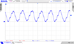
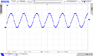
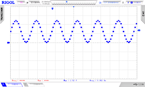
And here and three osci screens of our example (with a good filter 4th order for the PWM, see below). Offsets = 560, 256, 1; Frequencies: 4971 Hz, 2273 Hz, 8 Hz
Comparing resolutions
Here are some examples that show how the resolution can be increased by widening the phase accumulator:
| Width of phase accumulator N | 12 bit | 16 bit | 16 bit | 32 bit | 32 bit | 32 bit |
|---|---|---|---|---|---|---|
| Clock frequency fCLK | 36.363 kHz | 36.363 kHz | 100 kHz | 36.363 kHz | 100 kHz | 1 MHz |
| Maximum offset (fout = fCLK) | 4095 | 65635 | 65635 | 4294967295 | 4294967295 | 4294967295 |
| Resolution | 8.877 Hz | 0.554 Hz | 1.525 Hz | 0.000008.466 Hz! | 0.000023.283 Hz | 0.00023.283 Hz |
| Offset for 1 KHz | 113 | 1802 | 656 | 118113668 | 42949672 | 4294967 |
Arduino Uno
Now let's try with a bigger wave-table. Here an example to get a sinus with 1000 Hz.
    /* dds_arduino_uno_256v_8b.ino
     * weigu.lu
     * N = 32, P = 8, B = 8, res = 0.000008.466 Hz
     * 1kHz Sinus DDS
     * PWM output on pin 11 connected to low-pass
     * offset = fout*2^N/fCLK = 1000Hz*2^32/36363Hz = 118113668
     */

    #include "sine_table_256_values_8_bit.h"

    const uint8_t PIN_PWM_TIMER2A = 11; // PWM output on Uno
    uint32_t phase_offset = 118113668;
    uint32_t phase_accumulator = 0x00000000;
    uint8_t  address_pointer = 0x00;

    /* Timer1 interrupt calculates the pointer, gets the value
      for the PWM from the table and outputs it */
    ISR(TIMER1_COMPA_vect){
      phase_accumulator = phase_accumulator + phase_offset;
      address_pointer = phase_accumulator >> 24; // shift 3 byte
      OCR2A = SINE_256V_8B[address_pointer];
    }

    void setup() {
      pinMode(PIN_PWM_TIMER2A, OUTPUT);
      cli();         // stop interrupts
      /* Set Timer2 register to FastPWM */
      TCCR2A = 0xA3;
      TCCR2B = 0x01; // no prescaling (f_PWM = 16MHz/256 = 62,5kHz)
      /* Set Timer1 for Timer interrupt */
      TCCR1A = 0;
      TCCR1B = 0x0A; // turn on CTC mode prescaler = 2
      OCR1A = 54;   // f = 2MHz / (OCCR1A + 1) = 36363Hz
      TIMSK1 = 0x02; // enable timer compare interrupt
      sei();         //allow interrupts
    }

    void loop() { // everything in the ISR
    }
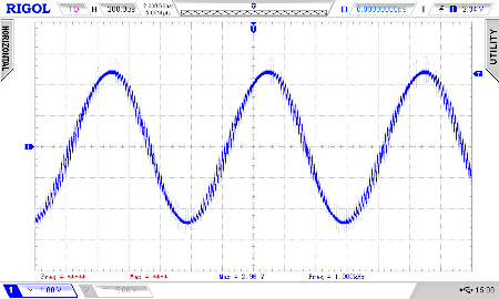
We see that the resulting waveform is not satisfying with our low pass filter (right image). The PWM frequency of 62.5 kHz is not sufficiently suppressed. We need a better filter (left image).
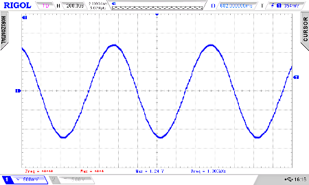
Here is the circuit for a Sallen-Key low-pass filter 4 order (fcutoff = 20 kHz):
By wobbling (0-70 kHz) the normal low-pass and the filter 4 order, we see the difference.
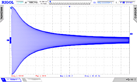
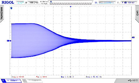
To finish this little tutorial let's use a Teensy 4.0 or 4.1 instead an Arduino Uno with a higher PWM frequency and resolution:
    /* dds_teensy_4_0_4096v_10b.ino
     * weigu.lu
     * N = 32, P = 8, B = 10, res = 0.00023283Hz!
     * 1kHz Sinus DDS
     * PWM output on pin 4 with 10 bit and 146.48kHz connected to low-pass
     * ISR with 1MHz
     * offset = fout*2^N/fCLK = 1000Hz*2^32/1000000Hz = 4294967
     */

    #include "sine_table_4096_values_10_bit.h"

    const uint8_t PIN_PWM = 4; // PWM output
    const uint8_t PWM_RESOLUTION = 10; // PWM output
    uint32_t phase_offset = 4294967;
    uint32_t phase_accumulator = 0x00000000;
    uint16_t  address_pointer = 0x0000;

    IntervalTimer myISR; // Create an IntervalTimer object

    /* Timer interrupt calculates the pointer, gets the value
      for the PWM from the table and outputs it */
    void isr_DDS() {
      phase_accumulator = phase_accumulator + phase_offset;
      address_pointer = phase_accumulator >> 22; // shift 22 bit
      analogWrite(PIN_PWM,SINE_4096V_10B[address_pointer]);
    }

    void setup() {
      analogWriteFrequency(PIN_PWM, 146484.38);
      analogWriteResolution(PWM_RESOLUTION);
      myISR.begin(isr_DDS, 1);    // 1µs -> 1Mz
      //myISR.priority(0);        // highest priority
    }

    void loop() { // everything in the ISR
    }
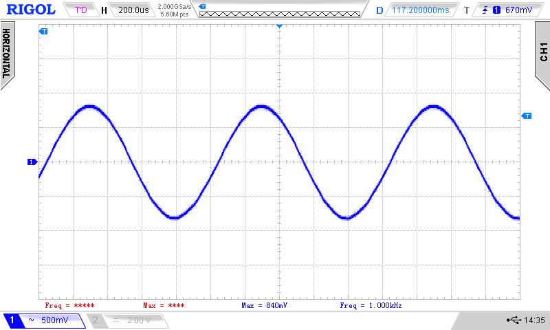
For good audio quality, the PWM solution is not a good solution on Teensy 4.0. We have many other options, like an external output devices via I2S (external DAC, Teensy Audio shield) or the built-in digital output S/PDIF. Another good option would be a Teensy 3.6 with internal DAC:
    /* dds_teensy_3_6_dac_4096v_10b.ino
     * weigu.lu
     * N = 32, P = 8, B = 10, res = 0.00023283Hz!
     * 1kHz Sinus DDS
     * DAC output on pin A21 (DAC0)
     * ISR with 1MHz
     * offset = fout*2^N/fCLK = 1000Hz*2^32/1000000Hz = 4294967
    */

    #include "sine_table_4096_values_10_bit.h"

    const byte DAC1 = A21;
    const byte DAC_RESOLUTION = 12;
    uint32_t phase_offset = 42949670;
    uint32_t phase_accumulator = 0x00000000;
    uint16_t  address_pointer = 0x0000;

    IntervalTimer myISR; // Create an IntervalTimer object

    /* Timer interrupt calculates the pointer, gets the value
      for the PWM from the table and outputs it */
    void isr_DDS() {
      phase_accumulator = phase_accumulator + phase_offset;
      address_pointer = phase_accumulator >> 22; // shift 22 bit
      analogWrite(DAC1,SINE_4096V_10B[address_pointer]);
    }

    void setup() {
      analogWriteResolution(DAC_RESOLUTION);
      myISR.begin(isr_DDS, 1);   // 1µs -> 1Mz
      //myISR.priority(0);       // highest priority
    }

    void loop() { // everything in the ISR
    }
Downloads
Interesting links
