3D printing
last updated: 2024-06-30
* under construction *
Voron 2.4 r2 pro+ built
Quick links
- Introduction
- BOM
- Wiring diagram and housing
- Configuring everything
- Config.g
- Final touch
- Downloads
- Interesting links
Introduction
I had to print some bigger pieces and my standard Felix profile showed me a build time of 66 hours. Perhaps I could tweak the profile to do it in half of the time, but even 33 hours are not appealing. I saw in the net that newer printer (prusa, bambu lab, voron) are able to do the print much faster in goog quality.
As I like open source projects and easily modable projects I chose the Voron 2.4 300x300 printer.
To gain time and after reading some reviews, I ordered the Voron 2.4 R2 Pro+ CoreXY 3D Printer Kit with M8P+CB1 Board and Canbus Wiring System from formbot3d.com. I also ordered the 3d printed pieces at formbot.
And whoa, what a kit. I knew I had a lot of work to do, but I completely underestimated the build!
The standard building instructions have 263 pages. Plus the instructions for the print head (Stealthburner, 73 pages) and other instructions for the tap (nozzle-based z-probe 48 pages, the motherboard (bigtreetech Manta-M8P V1.1 39 pages), the raspberry pi replacement (bigtreetech CB1 22 pages), the CAN board in the print head (bigtreetech EBB SB2209 CAN V1.0(RP2040) 46 pages), the display (bigtreetech HDMI5 9 pages).
In total, there are at least 500 pages to read. In addition, there are many videos and possibly Internet pages on mods to view that need to be looked at.
The first step was to get an overview and put many pieces of the puzzle together. But what can I say. I had a lot of fun and the result is really impressive.
So that I don't forget everything again and to help others, I will document a few things here.
Update: There is now a video on the formbot3d site from Butter Pockets Prints (BPP) that helps a lot. It would have saved me many hours :). There is also a wiring diagram that I missed that shows explicitly the wiring.
The Kit
The kit is really outstanding. Everything is included in sufficient quantity and very well labelled. The 3D parts are cleanly printed and the dimensions are correct.
Two minimal problems. A small plastic part on the print head was wrong (the cut-out for the USB connector was missing) and the M5 T-nuts were of poor quality. They could only be pressed into the aluminum extrusions with great effort.
You can look where T-Nuts must be inserted into the aluminum extrusions and do it before assembling the frame!! This allows the T-nuts to be inserted instead of pressed in.
The mainboard
The mainboard used for this printer comes from bigtreetech and is called Manta M8P V1.1. The mainboard with motor and fan driver, sensors etc has also a CAN bus interface to simplify cabling and a connecter to add a raspberry pi compute module to the mainboard. In the kit we have a replacement for the raspi module called CB1. The manuals for the mainboard and CB1 are here: https://github.com/bigtreetech/Manta-M8P and here: https://github.com/bigtreetech/CB1.
A little USB digression
Important mainboard V1.1 added functions are CAN interface(2Pin*2 XH2.54)and USB port function selection(UART to USB,USB OTG).
The mainboard has 2 USB 2.0 connector, one USB-C connecter and a USB to CAN bridge. Here a little digging in the schematic (file "BIGTREETECH MANTA M8P V1.1-SCH.pdf" in the Hardware section of the Manta board on github), to understand how this works:
We find an USB 2.0 HIGH SPEED 4-PORT HUB CONTROLLER (FE1.1S-QFN24) with 4 downstream ports and one upstream port. The upstream port USBH (USBHN(D-)/USBHP(D+), DMU/DPU) connects to an High-Speed USB 2.0 1:2 Mux/Demux Switch RS2227. This switch is an double-pole/double-throw (DPDT) analog switch
and is controlled by a signal from the CB1 called USBOTG_ID.
and comes from the CB1 (raspi) USB port USB2. The second output of the switch is USBD that connects to the new switch SW2. The switch
USBN (D-) and USBP (D+) of downstream port 4 on an
USBOTG_ID
V1.1 added functions CAN interface(2Pin*2 XH2.54),USB port function selection(UART to USB,USB OTG)
Push the DIP switch 4 (USB OTG) and 3 (RPIBOOT) to ON to enter BOOT mode.
When the writing is completed, push the DIP switch 4 (USB OTG) and 3 (RPIBOOT) back to OFF after power off, and power on again to enter the normal working mode.
In the schematic we see that these microcontroller pins are connected to the USB pins of CB1 (look here)
USBN (D-) and USBP (D+) of downstream port 4 on an USB 2.0 HIGH SPEED 4-PORT HUB CONTROLLER (FE1 .1S-QFN24). The upstream port (DMU/DPU) connects to an High-Speed USB 2.0 1:2 Mux/Demux Switch RS2227 and comes from the CB1 (raspi) USB port USB2.
MANTA M8P is designed with a USB 2.0 Hub, in order to save power consumption, the USB port of CM4 is disabled by default. If you want to enable it, you need to add the following content to the config.txt file: dtoverlay=dwc2,dr_mode=host
Setting up the mainboard (Manta M8P V1.1) and the toolhead PCB (EBB SB2209 CAN RP2040)
As we need the CB1 (raspi) later to flash a microcontroller, it is a good start to fix the CB1 to the mainboard and set it up.
But first we set the jumpers right. For the 6 stepper we set the jumper to UART Mode (P14) and VBB. Look at the formbot3d wiring diagram here: https://drive.google.com/file/d/1Cq7LWvDv7ZkAo8UH1fZQUC-eRevE1t4u/view?usp=sharing or the docs: https://docs.vorondesign.com/build/electrical/v2_m8p_wiring.html I used motor 1-3 and 5-7 (doc page)!. Now add the 6 motor driver. Set also the jumper for 120 Ω above the CAN interface headers and the jumpers for your fan voltages!
Remove the kapton tapes from the fixation holes on the mainboard. Add the thermal pad, the heat sink and the WiFi antenna to the CB1 and fix it on the mainboard.
Now we flash the operating system on an µSD card (32 MB) with the raspi imager (CB1 manual P15). It is a special image from bigtreetech! not the normal raspi image. I used the bigtreetech image and not the image BPP uses in the video. On the bigtreetech image klipper is already installed!
If you need WiFi you must add your credentials to the system.cfg file on the FAT32 partition.
After inserting the card to the mainboard (SOC card slot on the long side, not the MCU slot for the mainboard firmware!) we set the jumper to power the board over USB (P13 manta manual, don't forget to remove this jumper later when powering with the 24 V PSU!).
Connect the USB-C connector with 5 V to boot the CB1, and add an Ethernet cable if you don't use WiFi.
Search with your router or nmap your IP address and connect to the CB1
sudo ssh biqu@192.168.xxx.xxx
The password is "biqu".
As I like to use a fixed IP address, I added the following to the /etc/NetworkManager/system-connections/myssid.nmconnection file:
    [ipv4]
    address1=192.168.1.100/24,192.168.1.1
    dns=192.168.1.1
    dns-search=
    method=manual
Update and upgrade your software. If you like install other tools like mc or htop:
    sudo apt update && sudo apt upgrade
    sudo apt install mc htop
Installing the mainboard and toolhead firmware
Ok here I had some issues. I installed the firmware via SD card as showed in the Manta manual, and was able after some tweaking to run the printer. When I tried later to update the firmware I got problems with the CAN bus disappearing. In the beginning I did not really understand what I was doing, so here a short explanation.
We get two microcontroller (MCU), the Manta mainboard controller (STM32G0B1) and the toolhead controller (RP2040). They both need a klipper firmware compiled with CAN bus features. To be able to easily update later the firmware via CAN bus without opening the printer or toolhead to press buttons, we will flash a special bootloader for CAN nodes called katapult. So first we flash katapult on the chips and then only the klipper firmware.
The CB1 (Raspi) will talk to the mainboard via an USB to CAN bridge. We also need to set up the can bus on the CB1.
Building katapult bootloader and klipper firmware for the mainboard
We get the software from github and start menuconfig:
    cd ~
    git clone https://github.com/Arksine/katapult
    cd katapult
    make menuconfig
Choose the following configuration (we use a CAN bus speed of 1 MHz):

We see that the bootloader will use 8 KiB of memory and the CAN bus interface is on the Pins PD12 and PD13. This can be verified pin-out diagram in the manual (also in in the file "BIGTREETECH MANTA M8P V1.1 PinOut.png" in the Hardware section of the Manta board on github).
Press q to exit, and Yes to save. The configuration is saved as .config in the katapult directory. Run the make command to build the firmware:
    make clean
    make
The file katapult.uf2 file will be generated in home/biqu/katapult/out folder when make is finished.
Next we compile the klipper firmware. First we update klipper by running the "klipper Installation and Update Helper" kiauh script.
    cd ~/kiauh
    ./ kiauh.sh
I think the script is self explaining.
Next we compile the klipper firmware:
    cd ~/klipper
    make menuconfig
Choose the following configuration (again 1 MHz):

Here we define the USB to CAN bridge on PA11/PA12. In the schematic file "BIGTREETECH MANTA M8P V1.1-SCH.pdf" in the Hardware section of the Manta board on github we see that these microcontroller pins are connected to the USB pins of CB1 (look here)
Press q to exit, and Yes to save. The configuration is saved as .config in the klipper directory. Build the firmware:
    make clean
    make
Flashing katapult bootloader and klipper firmware to the mainboard
We flash katapult to the mainboard via DFU-protocol (Device Firmware Upgrade). Naturally the Chip already has a bootloader and we initiate the DFU protocol by pressing and holding the boot0 button on the mainboard, then pressing shortly reset and than letting go of boot0. With the list usb command we see if we did it right.
lsusb
The USB device with ID 0483:df11 should list as STMicroelectronics STM Device in DFU mode.
Now we flash the bootloader with dfu-util as root (folder: /usr/bin/dfu-util):
sudo dfu-util -a 0 -D ~/katapult/out/katapult.bin --dfuse-address 0x08000000:force:leave -d 0483:df11
Hit reset on the mainboard and repeat boot0, reset, boot0 to initiate dfu mode a second time. Check with lsusb.
Now we flash the klipper firmware:
sudo dfu-util -a 0 -d 0483:df11 --dfuse-address 0x08002000 -D ~/klipper/out/klipper.bin
Again we reset the mainboard, and check with lsusb. And now we should see:

Getting CB1 ready for CAN
Now let's setup and test the CAN bus. For more infos on the CAN bus look at the links at the end of the page.
On the CB1 we create a file named can0:
sudo nano /etc/network/interfaces.d/can0
and add the following settings to the file:
    allow-hotplug can0
    iface can0 can static
      bitrate 1000000
      up ifconfig $IFACE txqueuelen 1024
Save with Ctrl+o and leave with Ctrl+x.
Bring up CAN network with sudo ifup can0 or reboot.
With ifconfig or the following command we should see that CAN is running:
ip -s -s link show dev can0
Now we query can0 to see if mainboard shows up with a UUID:
python3 ~/katapult/scripts/flash_can.py -q
Now you should see something like this:

!Note this UUID somewhere, because you need it to set up your printer! and later it may be difficult to find it (no more visible if klipper is running, even if stopping klipper).
We will configure klipper in a later step!
Main Assembly Manual
Let's start with the main manual (AssemblyManual2.4r2.pdf). The documents can be fount on github: https://github.com/VoronDesign/Voron-2.
The beginning is straightforward. You have to print the rail guides (MGN9railguidex2.stl and MGN12railguidex2.stl) and the distance guide for the stepper (pulley_jig.stl) yourself, because they are not in the kit. You find them in the STLs folder under Tools.
In the gantry section (P84) you don't need the cable chains because we use only one cable with CAN bus from the extruder to the back of the chamber. So we also have to use shorter screws on the X axis (P104), M5x10 BHCS instead M5x16 BHCS (do not mount the cable chain holder).
The X-end-stop will be mounted on the extruder and we do not need the option HALL ENDSTOP (P110, P113).
An important step is "SQUARING THE GANTRY" (P122). Look also at the page in the Voron docs: https://docs.vorondesign.com/build/mechanical/v2_gantry_squaring.html.
Next step is the fixation of the belts. As we use the Voron Tap, this replaces the X carriage (P129-130). It is a good idea to built the Voron Tap before continuing.
Voron Tap
We use the Tap manual that you find here: https://github.com/VoronDesign/Voron-Tap. In this manual you find the explanation how the Tap works. I have the RC8 version. If you use this version also Look at the R8_errata.md file!
I had the problem, that the magnets in combination with the M3x6 FHCS screws (P27) were not strong enough to reset the Tap, so i removed the screws and replaced them with to magnets as suggested in the errata file. The X-endstop (X-Axis_Switch (Trident Style) P30) is fixed to the Tap same as the optical sensor for the Tap itself.
Now fix the A/B belts (main manual). and add the Tap. Ignore P143-145.
The next step is the Voron Stealthburner toolhead.
Voron Stealthburner
Again another (even two :)) manuals. The Stealthburner manual is here: https://github.com/VoronDesign/Voron-Stealthburner.
Stealthburner is the toolhead with the extruder and the hotend. It come's in 3 parts. The part that moves the filament is called ClockWork2 Extruder. It contains the stepper motor. The part with the hotend is called Tool Cartridge. The third part is the cover with the fans and the LEDs and it is called StealthBurner (P9). The separate ADXL sensor is not needed, at it is contained on the PCB of for the CAN bus.
EBB
And here comes the second manual! As we use only one cable (CAN Bus) we need a microcontroller inside the toolhead controlling everything (fans, motor, sensors, LEDs). This is done with the EBB from bigtreetech, the company that also provides the motherboard (Manta 8P), the raspberry pi substitute (CB1) and the display (HDMI5).
I got the version with the raspberry pi microcontroller RP2040 and SB2209 motor driver (EBB SB2209 CAN (RP2040)): https://github.com/bigtreetech/EBB.
The microcontroller needs a firmware, and it is a good idea to flash it before fixing it in the toolhead. First we will flash a firmware called "katapult" (the older name was CanBoot). You find it here: https://github.com/Arksine/katapult. This is a custom firmware that allows flashing the needed klipper firmware to the EBB via the CAN network so there is no more need to plug a USB cable to flash/update klipper (katapult is handy but not mandatory).
The next step is documented in the EBB manual (P25).
The firmware will be flashed over the CAN bus, so we need to set jumpers for the CAN bus termination resistances of 120 Ω on both sides of the bus. We've already done this on the motherboard, but we need to do it also on the EBB board (P10 in the EBB manual).
To actually create a CAN network in your system, your Pi needs some sort of device to act as a CAN adapter (think of it like a USB network card, or USB wifi dongle). The simplest plug-and-play option is to use a dedicated USB to Can device such as the BigTreeTech U2C, Mellow Fly UTOC, Fysetc UCAN, etc. (other devices exist as well). The second “cheaper” option is to actually utilise your printer mainboard (ie. Octopus or Spider board) to function as a usb-can bridge for klipper. We’ll cover both options, but you only need to choose one.
sudo systemctl start klipper sudo systemctl stop klipper sudo systemctl status klipper
The next steps are similar to compiling the motherboard firmware:
    cd ~
    git clone https://github.com/Arksine/katapult
    cd katapult
    make menuconfig
Choose the following configuration (we use a CAN bus speed of 1 MHz):

Press q to exit, and Yes to save. The configuration is saved as .config in the katapult directory. Run the command
    make clean
    make
https://hackaday.com/2025/03/21/cheap-endoscopic-camera-helps-automate-pressure-advance-calibration/
Download it onto your computer using the SSH application.
If you want to get or see the UUID for the EBB, you have to first stop klipper. Once a device is 'claimed' it will no longer show up on the query.
sudo systemctl stop klipper ~/klippy-env/bin/python ~/klipper/scripts/canbus_query.py can0 sudo systemctl start klipper
Note: Please note that katapult is designed for the purpose of directly updating the MCU firmware via the CAN bus interface. If you prefer the DFU update method, you may skip this step. “Flashing katapult on a CB1/Raspberry Pi”
~/katapult/scripts/flashcan.py -i can0 -q or ~/klippy-env/bin/python ~/klipper/scripts/canbusquery.py can0
9: make klipper for the M8P
cd ~/klipper/ make menuconfig
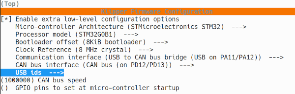
[*] Enable extra low level configuration options Micro controller Architecture (STMicroelectronics STM32 ) Processor model (STM32G0B1 ) Bootloader offset 8 KiB bootloader) Clock Reference (8 MHz crystal) Communication interface (USB to CAN bus bridge (USB on PA11/PA12)) CAN bus interface (CAN bus (on PD12/PD13)) (500000) CAN bus speed
make clean make
10: Enter DFU mode. Hold BOOT and tap RESET, then let go of BOOT. There will be no notification that it went into DFU mode but it shoud have if you did the sequence.
11: flash the firmware. make flash FLASH_DEVICE=0483:df11
12: check the UUID and copy it down. ~/klippy-env/bin/python ~/klipper/scripts/canbus_query.py can0
13: make klipper firmware for the EBB cd ~/klipper/ make menuconfig input the info for your ebb make clean make
14: flash the ebb
python3 ~/katapult/scripts/flashcan.py -i can0 -f ~/klipper/out/klipper.bin -u PutYourUUIDHere
https://www.klipper3d.org/CANBUS.html#host-hardware
For Stealthburner missing needlebearing 357
Stealthburner Manual 14 -cable chain holder not needed
Dragon high flow hotend code P-DRG https://www.youtube.com/watch?v=WMeTM9SB8Jc 4x M2.5x8mm Remove the screws attaching the groove-mount adaptor to access the hard mounting points. https://github.com/VoronDesign/Voron-Stealthburner/blob/main/STLs/Stealthburner/Printheads/README.md
Wrong piece to fix CAN cable. No space for USBC header. Used this: https://github.com/bigtreetech/EBB/blob/master/EBB%20SB22402209%20CAN/STL/PrintedPartforCANCable_V1.2.stl
Length of scews tio fix the rail not correct: M3x12 instead of M3x8 and M3x16 instead of M3x12! add M3x50 stiffeners
x endstop on stealthburner Y endstop on A motor mount
Updating klipper
https://mpx.wiki/
On the CB1 (raspi)
- The updates can be done in the web interface under the
MACHINEtab. - Another possibility is to use the "klipper Installation and Update Helper" kiauh script.
    cd ~/kiauh
    ./ kiauh.sh
On the Manta M8p mainboard
Make the klipper firmware
    cd ~/klipper
    make menuconfig
Choose the following configuration (we use a CAN bus speed of 1 MHz):
Press q to exit, and Yes to save. The configuration is saved as .config in the klipper directory. Run the command
    make clean
    make
Setting Manta to DFU mode via katapult script
On CB1 (ssh) we type the following command (replace printer.cfg file).
python3 ~/katapult/scripts/flashtool.py -i can0 -u <uuid> -r
The output is:
Sending bootloader jump command...
Bootloader request command sent
Flash Success
lsusb
and you should se the following line:
Bus 002 Device 006: ID 0483:df11 STMicroelectronics STM Device in DFU Mode
We use the ID of the USB device (0483:df11) to flash klipper with:
$ make flash FLASH_DEVICE=0483:df11
sudo dfu-util -a 0 -D ~/klipper/out/klipper.bin --dfuse-address 0x08000000:force:mass-erase -d 0483:df11
but nothing is flashed! Now type
cd ~/klipper $ make menuconfig
I ran into basically this same issue. This isn't mentioned anywhere in the SB2240 manual, but this guy on YouTube explained that the SB2240 comes with a built-in MAX31865 for measuring your PT1000 over SPI. All that to say that your sensor_type: MAX31865 is actually correct. I finally got mine running with a 2-wire PT1000 on the SB2240 with almost exactly what you had:
sensor_type: MAX31865
sensor_pin: EBBCan:gpio9
spisoftwaresclk_pin: EBBCan:gpio10
spisoftwaremosi_pin: EBBCan:gpio8
spisoftwaremiso_pin: EBBCan:gpio11
rtdnominalr: 100
rtdreferencer: 430
rtdnumof_wires: 2
Note that your rtdnominalr has one more 0 than I have.
firmware restart doesn’t work as the SB2040 can’t be software restarted, must do a hard reset via a power cycle!
https://github.com/bigtreetech/EBB/blob/master/EBB%20SB2209%20CAN%20(RP2040)/sample-bigtreetech-ebb-sb-rp2040-canbus-v1.0.cfg
[stepperx] endstoppin: ebb:gpio24
tapklipperinstructions.md
https://github.com/MaffooClock/Voron-2/blob/main/klipper_config/manta-m8p.cfg
https://www.jonashietala.se/blog/2024/02/28/letsbuildavoronnoise/ https://www.klipper3d.org/TMCDrivers.html https://www.klipper3d.org/ConfigReference.html#tmc-stepper-driver-configuration
Nevermore Filter
Magnets too thick, Heating them to fit At around 80 °C, a magnet will lose its magnetic force and it will become demagnetized permanently if exposed to this temperature for a period, or if heated above its Curie temperature.
Changed bed distance to 43mm instead of 38mm (front edge of the print plate should sit 38mm behind the front edge of the frame).
Pins of fans only visible in png file!! EBB SB2209 CAN V1.0(RP2040)-Pin.png
Axial fan: VFAN1 stealthburner bottom (cenrifugal 50x50x15, 24V, 2 pin)
Hotend: VFAN1 GPIO14
Turbine fan: VFAN2 stealthburner top (cenrifugal 50x50x15, 24V, 2 pin)
VFAN2 GPIO13
RGB GPIO16 Tap Sensor (probe) GPIO22 Filament GPIO21 TH0 GPIO27
[temperaturesensor EBBNTC] sensortype: Generic 3950 sensorpin: ebb:gpio28
[adxl345] cspin: ebb:gpio1 spisoftwaresclkpin: ebb:gpio2 spisoftwaremosipin: ebb:gpio0 spisoftwaremisopin: ebb:gpio3 axes_map: z,-y,x
[tmc2209 extruder] uartpin: ebb:gpio20 runcurrent: 0.650 stealthchop_threshold: 999999
Configure klipper
printer.Config
[include mainsail.cfg]
host MCU service is preinstalled and ready to use with:
[mcu CB1] serial: /tmp/klipperhostmcu [include generic-bigtreetech-xxx.cfg]
https://github.com/bigtreetech/Manta-M8P/blob/master/V1.0_V1.1/Firmware/klipper/README.md
24V PSU (LRS-200-24, Meanwell) holder (marked with LRS 200) M4 instead of M3
Interesting links
- Mainboard Manta-M8P: https://github.com/bigtreetech/Manta-M8P
- Raspberry Pi replacement CB1: https://github.com/bigtreetech/CB1
- Formbot wiring diagram: https://drive.google.com/file/d/1Cq7LWvDv7ZkAo8UH1fZQUC-eRevE1t4u/view?usp=sharing
Voron docs jumper: https://docs.vorondesign.com/build/electrical/v2_m8p_wiring.html
I found more info in the klipper documentation: https://www.klipper3d.org/CANBUS.html#host-hardware and on two videos: https://youtu.be/AYnoJCH7JJc and https://youtu.be/EA-oBfenxAE, https://canbus.esoterical.online/.
AssemblyManual2.4r2.pdf: https://github.com/VoronDesign/Voron-2/blob/Voron2.4/Manual/Assembly_Manual_2.4r2.pdf
- Squaring the gantry: <https://docs.vorondesign.com/build/mechanical/v2_gantry_squaring.html.>
- Voron Tap manual:: https://github.com/VoronDesign/Voron-Tap/tree/main/Manual.
