3D printing
last updated: 2022-02-08
Quick links
- Introduction
- BOM
- Wiring diagram and housing
- Configuring everything
- Config.g
- Final touch
- Downloads
- Interesting links
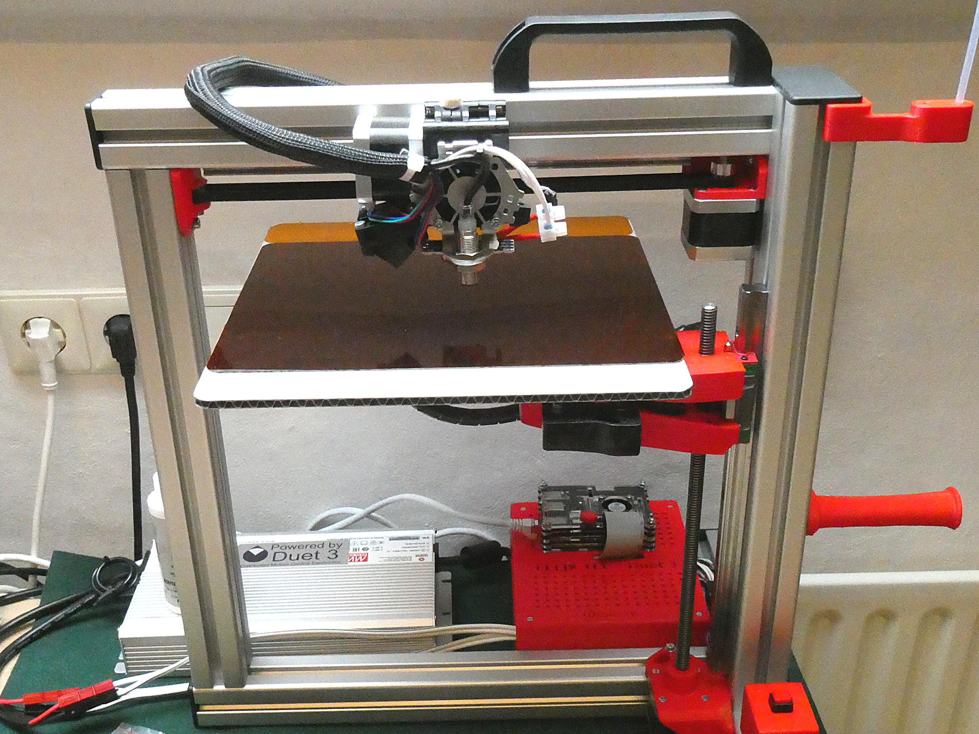
New Felix 3 with spare parts and a Duet3d motherboard
Introduction
After my upgrade of a Felix 4.1 dual head with a new Duet 3 6HC motherboard and a higher voltage I was really happy with the result.
As I had quite a bunch of spare parts from my old Felix 3 resulting from the updates, I decided to built a second Felix.
I bought a Felix 3 DIY kit in 2013, because it had good reviews and was fully open source. Unfortunately felixprinters decided to stop publishing the .stl files after the Felix 2. But I was lucky in misfortune because the Felix 2 files can be found in downloads and don't really differ from the newer parts.
I will not document the whole building process, but only some relevant things to remember and that could help other people building their own duet3 printer.
I will also not repeat all the infos that can be found on my other duet3 page: http://weigu.lu/other_projects/3d_printing/felix4dual_duet3/index.html. That page is more complete, so perhaps first read that page.
BOM
The frame was bought at
| no. | item | order number |
|---|---|---|
| 4x | Aluminiumprofil 40x40 schwer Nut 8 I-Typ Länge:400 mm | H1084040S |
| 1x | Aluminiumprofil 40x80 schwer Nut 8 I-Typ Länge:440 mm | H1088040S |
| 5x | Profilabdeckkappe 40x40 Nut 8 I-Typ | H208AK4040 |
| 1x | Profilabdeckkappe 40x80 Nut 8 I-Typ | H208AK8040 |
| 8x | Zentrierplattensatz Nut 8 I-Typ | H208ZPS |
| 40x | Halbrundschraube ISO 7380 Halbrundschraube: M4x8 | H208HS48 |
| 20x | Halbrundschraube ISO 7380 Halbrundschraube: M8x16 | H208HS816 |
| 20x | Halbrundschraube ISO 7380 Halbrundschraube: M8x12 | H208HS812 |
| 1x | Handgriff PA 145 Nut 10 B-Typ | H210HG145 |
| 10x | Nutenstein mit Steg Nut 8 M8 I-Typ | H208NSMS8 |
| 6 | Wunschbohrung in Profil für Verbindungstechnik Bohrung: Durchmesser 8 mm | Bohrung-BD8 |
| 6 | Wunschgewinde in Profil für Verbindungstechnik Gewinde: M8 | Gewinde-GWM8 |
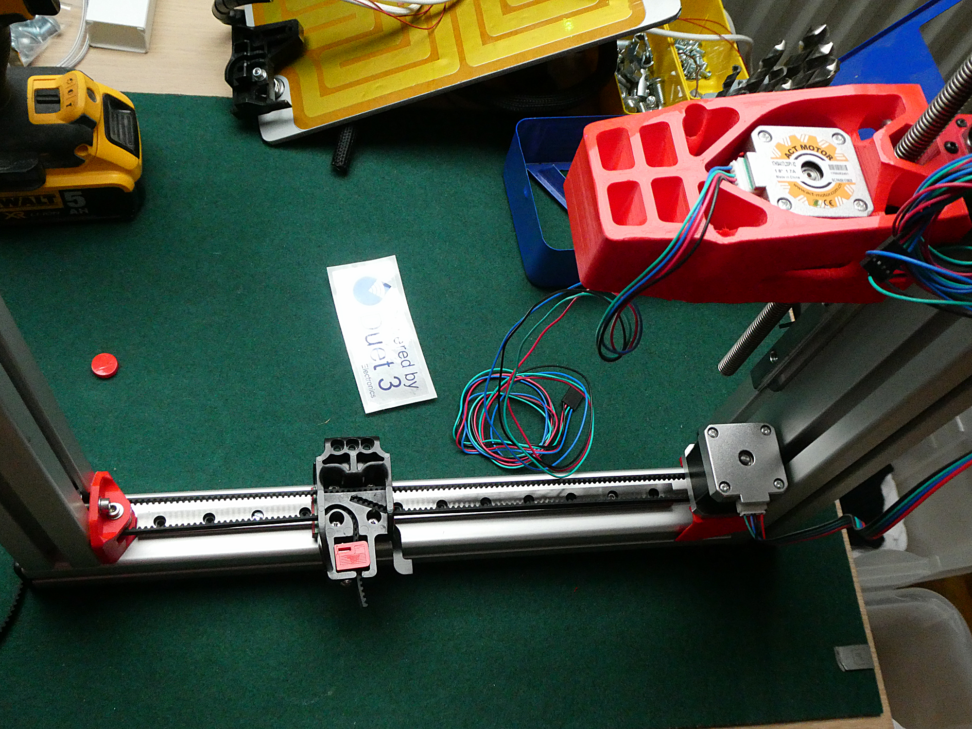
Further I needed 2 x MGN12H Mini Lineare Schienenführung that I found on Amazon, but the 135 002.0 Hiwin linear ball bearing - HGW15CC1R300Z0 had to be bought in the Felix shop.
To fix the x-axes linear guideway I didn't find nuts with M3 thread, so I enlarged the holes to 4 mm and took nuts with M4 thread. I grinded the head of M4 countersunk screws to fit the holes.
Some of the 3D printed parts where:
- z-axis-motor-bracket_v10_F2.STL
- z_axis_carrier_pt2_v11_F2_0.STL
- z_axis_carrier_pt1_v15_F2_0.STL
- x-stage-motor-bracket_v6_F2_0_export.gcode
- x-axis belt mount v6 F2_0.STL
- y-stage bracket pt4_v4.stl
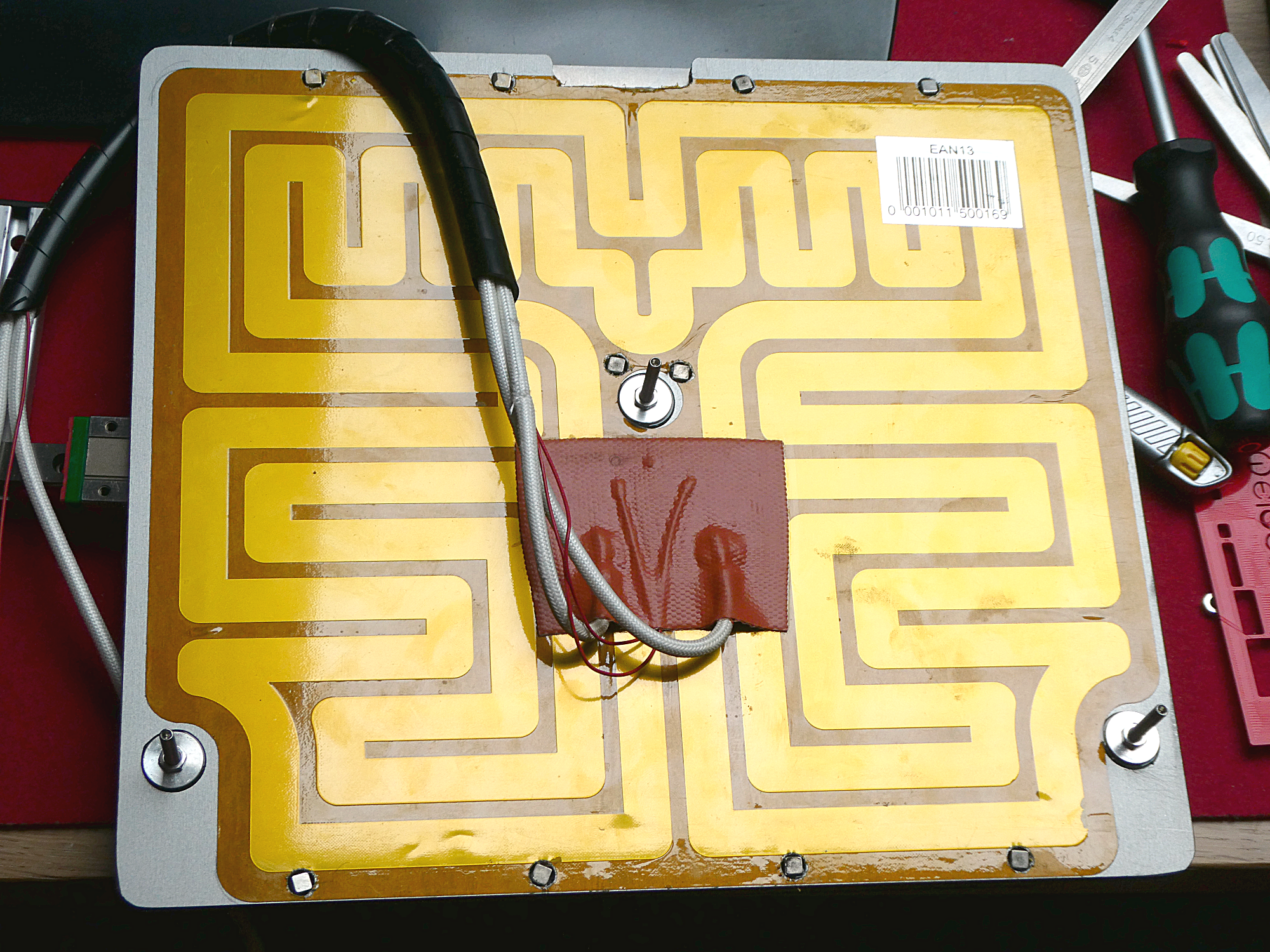
I drilled some holes in the Felix3 aluminium bed and glued some supermagnets to hold the Tec 4 - flexible build-plate (purchased at felixprinters).
To illuminate the bed I used an Neopixel stripe with 8 LEDs connected to the Neopixel header of the duet board. Connect the LED strips to the 4-pin connector labelled DS_LED. 5V and Ground and the data input line to the DS_DO pin of the Duet.
Naturally I also added a Shutdown button for the Raspberry Pi and an emergency button, especially useful while testing.
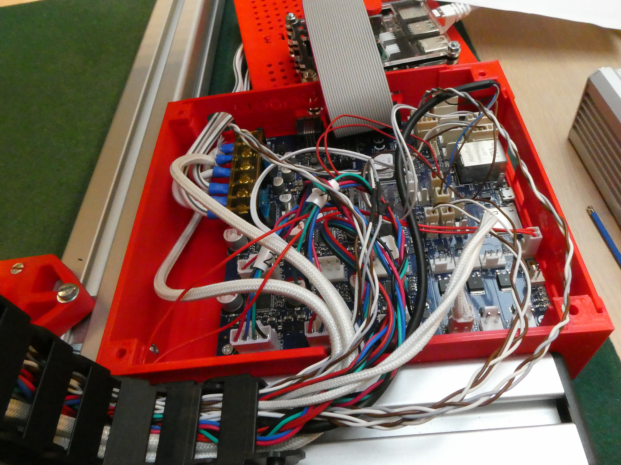
Wiring diagram and housing
Here is the link to the original Wiring Diagram. I used the following connections:

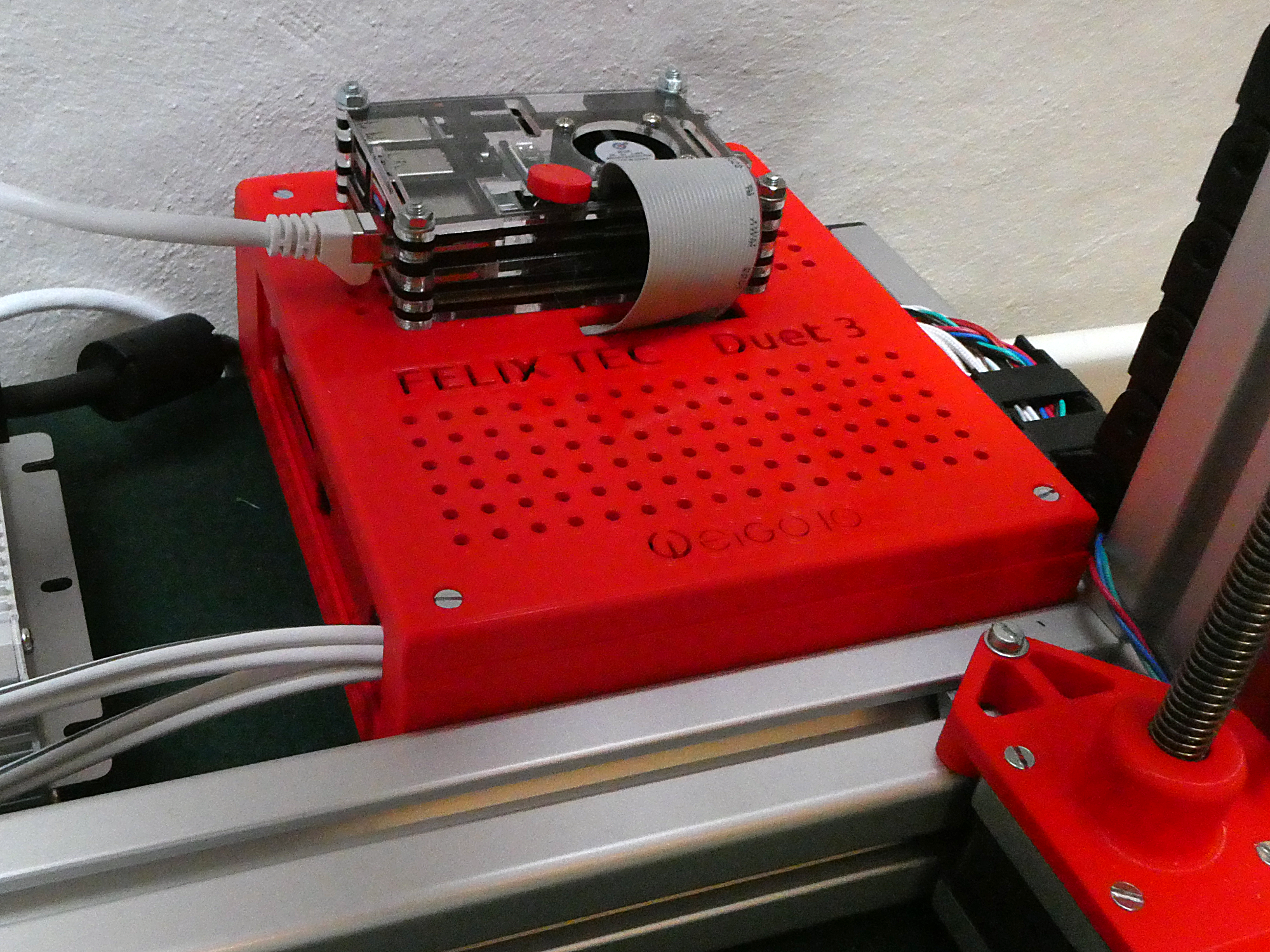
I created a new housing with Freecad. The Raspberry Pi sits on top of the housing.
Configuring everything
I took the config.g file from my other dual head printer and had to change only some things. Naturally I had first to delete the data for the second extruder (extruder, stepper, fan). Than I had to get the PID data for the heated bed and the extruder. With M303 H0 P0.75 S60 and M303 H1 P0.75 S190 I got the following answers:
    Auto tuning heater 0 completed after 3 idle and 7 tuning cycles in 1652 seconds. This heater
    needs the following M307 command: M307 H0 B0 R0.416 C318.2 D17.67 S0.75 V19.0
    Auto tuning heater 1 completed after 3 idle and 5 tuning cycles in 550 seconds. This heater
    needs the following M307 command: M307 H1 B0 R4.208 C197.3 D12.40 S0.75 V19.1
After this I had to calibrate the Z probe use the following link: https://docs.duet3d.com/User_manual/Tuning/scanning_z_probe_calibration.
Then to calibrate the bed I used the G32 command as described in the Manual Bed Levelling Assistant (MBLA) chapter: http://weigu.lu/other_projects/3d_printing/felix4dual_duet3/index.html#link_5. Here my adjusted bed.g file:
; bed.g
; called to perform automatic bed compensation via G32
G28                                ; home
M401                               ; deploy Z probe
M671 X148:40:40 Y101:233:-38 P0.5  ; adjusting screws bed middle, front and rear
G30 P0 X148 Y92 Z-99999            ; probe near an adjusting screw middle
G30 P1 X40 Y190 Z-99999            ; probe near an adjusting screw front right
G30 P2 X40 Y35 Z-99999 S3          ; probe near an adjusting screw rear right
                                   ; and report adjustments needed
M402                               ; retract probe
Config.g
So here the final config.g file:
    ; Configuration file for Duet 3 (firmware version 3.3)
    ; executed by the firmware on start-up
    ;
    ; generated by weigu.lu 2022-02-08

    ; General preferences
    G90                                               ; send absolute coordinates...
    M83                                               ; ...but relative extruder moves
    M550 P"duet3single"                               ; set printer name (must be Raspi host name!)

    ; Drives
    M569 P0.0 S0                                      ; physical drive 0.0 (X) goes backwards (S0)
    M569 P0.1 S1                                      ; physical drive 0.1 (Y) goes forwards
    M569 P0.2 S1                                      ; physical drive 0.2 (Z) goes backwards
    M569 P0.3 S0                                      ; physical drive 0.3 (E0) goes backwards
    M584 X0.0 Y0.1 Z0.2 E0.3                          ; set drive mapping
    M350 X16 Y16 Z16 E16 I1                           ; configure microstepping with interpolation
    M92 X76.19 Y76.19 Z1600.00 E164.00                ; set steps per mm
    M566 X600.00 Y600.00 Z18.00 E228.00               ; set maximum instant. speed changes (mm/min)
    M203 X12000.00 Y12000.00 Z600.00 E1800.00         ; set maximum speeds (mm/min)
    M201 X1100.00 Y1100.00 Z100.00 E10000.00          ; set accelerations (mm/s^2)
    M906 X1275 Y1275 Z1275 E1275 I20                  ; set motor currents (mA) and idle factor (%)
    M84 S20                                           ; Set idle timeout

    ; Axis Limits
    M208 X0:240 Y0:205 Z0:220                         ; set axis minima and maxima

    ; X and Y Endstops
    M574 X1 S1 P"io0.in"                              ; configure active-low endstop (X) pin io0.in
    M574 Y1 S1 P"io1.in"                              ; configure active-low endstop (Y) pin io1.in

    ; Z-Probe
    M558 P5 C"io6.in" H5 F60 T6000                    ; set Z probe type to unmodulated
                                                      ; and the dive height + speeds
    G31 P500 X7 Y35 Z1.49                             ; set Z probe trigger value, offset
                                                      ; and trigger height
    M557 X7:240 Y35:200 S20                           ; define mesh grid (use probe values!)
    ;M671 X110:40:40 Y94:231:-38 P0.5                 ; this is not needed here; look in bed.g

    ; Heaters
    ; bed
    M308 S2 P"temp2" Y"thermistor" A"S2" T100000 B4092; conf. sensor 2 (S2 bed) thermistor pin temp2
    M950 H0 C"out0" T2 Q50                            ; create bed heater out0, PWM freq to 50Hz
                                                      ; and map it to sensor 2 (T2)
    M143 H0 S105                                      ; set temperature limit for heater 0 to 105C
    M307 H0 B0 R0.416 C318.2 D17.67 V19.0 B0 S0.75    ; B0 = no bang-bang (PID) S0.75 = PWM limit
    M140 H0 R20 S55                                   ; map heated bed to heater 0
    ; left extruder                                   ; conf. sensor 0 (left ext.) thermistor temp0
    M308 S0 P"temp0" Y"thermistor" A"S0_Left" T100000 B4092
    M950 H1 C"out1" T0 Q250                           ; nozzle heater on out1, PWM freq to 250Hz
                                                      ; and map it to sensor 0 (T0)
    M143 H1 S275                                      ; set temperature limit for heater 1 to 275C
    M307 H1 B0 R4.208 C197.3 D12.40 S0.75 V19.1       ; B0 = no bang-bang (PID) S0.75 = PWM limit
    M570 H1 P5 T30                                    ; raise overshoot limit to 30°C (5s)

    ; Fans
    M950 F0 C"out7" Q5                                ; create fan 0 print cooling fan out7 pwm 5Hz
    M106 P0 C"print-cooling" S0.0                     ; set fan 0 value
    M950 F1 C"out8" Q5                                ; create fan 1 pin heatsink out8 and pwm 5Hz
    M106 P1 C"heat_sink" S1.0                         ; set fan 1 value

    ; Tools
    M563 P0 D0 H1 F0 S"T0_Ex_Left"                    ; define tool T0 (felix: left ext.) D0=Drive 3
    G10 P0 X-12.19 Y0 Z0                              ; set tool 0 axis offsets
    G10 P0 R120 S185                                  ; set initial tool 0 active, standby temp. 120C

    ; weigu.lu
    M950 E0 C"led" T1 Q3000000                        ; create Neopixel on LED port SPI frequency 3MHz
    M150 E0 R128 U128 B128 S8                         ; Neopixel LEDs
    M144                                              ; switch bed to standby at startup
Final touch
We have a neopixel stripe with 8 LEDs. Look here for the commands: https://docs.duet3d.com/User_manual/Reference/Gcodes.
I use the commands: M950 E0 C"led" T1 Q3000000 and M150 E0 R128 U128 B128 S8.
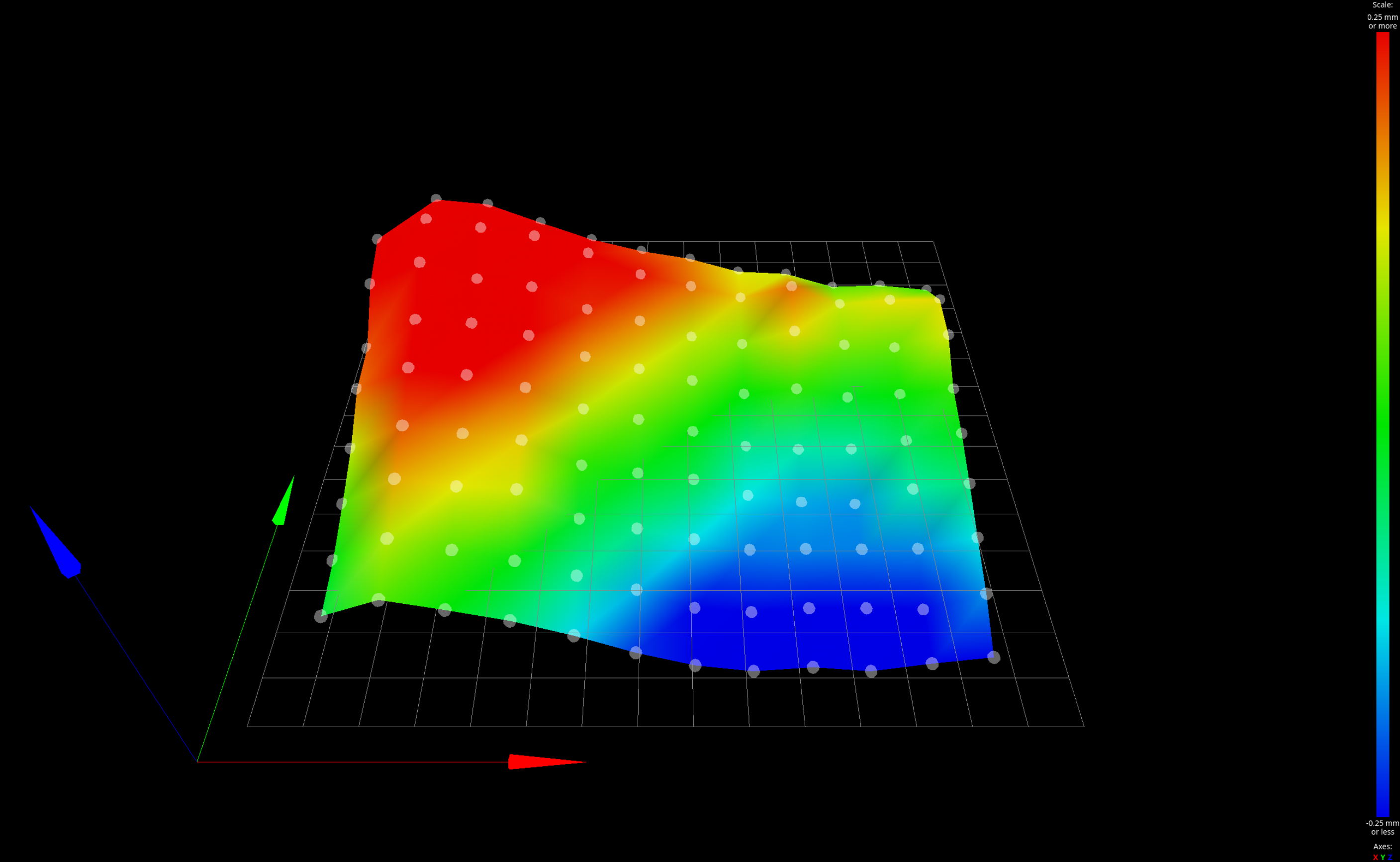
In the end I created a heatmap with the G29 command. Look at the Mesh Bed Compensation (MBC): http://weigu.lu/other_projects/3d_printing/felix4dual_duet3/index.html#link_6.
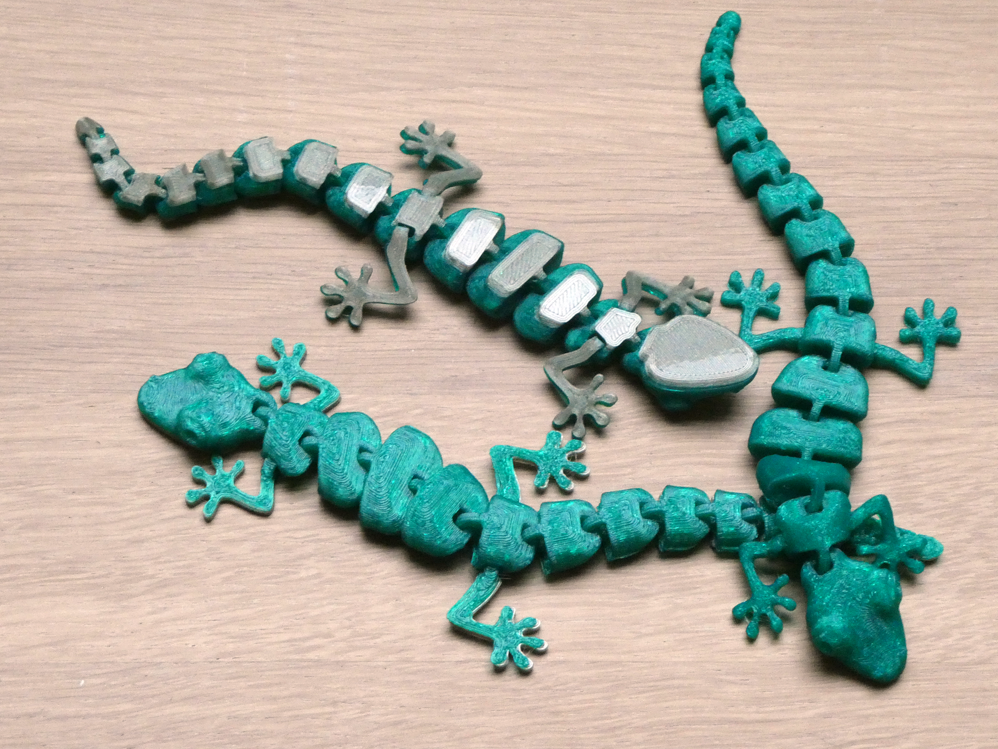
First test prints:
Downloads
- Config files and STL files on github: https://github.com/weigu1/felix_goes_duet3
Interesting links
- https://github.com/Duet3D
- https://docs.duet3d.com/User_manual/Overview/Getting_started_Duet_3_MB6HC
- https://docs.duet3d.com/User_manual/Machine_configuration/SBC_setup
- https://docs.duet3d.com/How_to_guides/Wiring_your_Duet_3
- https://docs.duet3d.com/User_manual/Connecting_hardware/IO_E_stop
- https://docs.duet3d.com/User_manual/RepRapFirmware/RepRapFirmware_overview
- https://docs.duet3d.com/User_manual/Connecting_hardware/Z_probe_connecting
- https://docs.duet3d.com/User_manual/Tuning/scanning_z_probe_calibration
- https://docs.duet3d.com/User_manual/Connecting_hardware/Heaters_tuning
- https://docs.duet3d.com/User_manual/Reference/Duet_Web_Control_Manual
- https://docs.duet3d.com/User_manual/RepRapFirmware/RepRapFirmware_overview
- https://reprap.org/wiki/List_of_Firmware
- https://github.com/MarlinFirmware/Configurations/archive/release-2.0.6.zip
- https://dyzedesign.com/2019/04/differences-12v-24v-3d-printer/
- https://reprap.org/wiki/Thermistor
