Tutorials:
Sensors, interfaces and bus systems (SENIN, BUSSY)
Buses
last updated: 2023-12-06
Quick links
Introduction
Song(s) of this chapter: Bob Marley and the Wailers > Babylon by Bus (whole album)
TIA-232 has a point to point connection and is seldom used as bus system.
If more interfaces share the same medium, we call this a bus. A mainboard has a system bus to interconnect the major components of the computer system. In a Local Area Network (LAN) one of the network topologies is the Bus network where all the nodes are connected to a single cable (called backbone).
We will look here at the Buses mostly used by IoT devices to connect to other devices or sensors and actuators, namely I²C, SPI and 1-Wire.
In a bus every device will get all the information. The time in communication must be shared, and this time must be assigned to avoid collisions. Normally this is done by a master. The other devices are called slaves. Each device has an individual address. Master/slave buses (e.g. I²C-Bus, SPI) are often synchronous and it is the the master that supplies the timing clock signal.
There exist also multi-master buses. An arbitration scheme must take care of conflicts (two masters need the bus at the same time).
In this chapter we will use a single-board computer instead of microcontroller to connect to sensors, actuators or other devices. The most known sb-computer is the Raspberry Pi. The Raspberry Pi is a cheap computer that runs Linux (Raspi OS, debian, ubuntu), but it also provides many general purpose input/output pins (GPIO) and interfaces (Serial, SPI, I²C).
All over the world, Raspberry Pi's are used in schools to learn programming skills and build hardware projects. A Raspberry Pi is cheap, but nevertheless a fully functioning computer. The Raspberry Pi is also often used in home automation, and more and more in industrial applications.
The GPIO's of the Raspberry Pi are less robust than the GPIO's of microcontroller. A wrong voltage could destroy the computer. We can use additional hardware to protect the GPIO's like the raspi buffer board, or an I/O port-expander chip like the PCF8574 or MCP23017 for I²C to create more robust GPIO's.
Using the Raspberry Pi (Raspi)
The operating system of the Raspberry Pi is running on an SD card. Since 2020 it is called Raspberry Pi OS instead of Raspian. We will use the desktop version, because it is easier to write python code using the Thonny IDE.
Burn the image and enable ssh
The Raspberry Pi Imager is open source (https://github.com/raspberrypi/rpi-imager) and facilitates the creation of the µSD card. Download it (https://www.raspberrypi.com/software/) and install it on your computer (Linux: snap install rpi-imager).
We choose the Raspi OS (32 bit) and our SD card (take a look at the other options; even Libreelec (Kodi) or octopi can be installed immediately :)).
In the Imager the advanced menu can be reached by clicking on the gear wheel icon.
In the advanced menu we can enable ssh, set the Raspi hostname, the Wifi country, SSID, and password, and the locales. (don't forget to scroll!).


For security reasons, ssh (secured access over network) is no longer enabled by default on the Raspi, so our headless (without keyboard, mouse and or screen) Raspi can't be accessed. So enable ssh. Set the raspberry username and the password. Don't use "pi" and "raspberry" because everybody knows the old standard username and password!
Now we can ssh to our Raspi by using the username (iot) and the hostname (e.g. pi-iot-100) with the .local extension:
sudo ssh iot@pi-iot-100.local
After this, log in with your username and password.
Ups, I forgot to set a hostname
To find the IP address of the Raspi we can use the nmap command. If not installed, install nmap (linux: sudo apt install nmap), Windows download setup.exe here. Look for your Raspi with a ping scan:
sudo nmap -sP 192.168.130.142/24
Zenmap is a GUI for nmap and can also be used.
Look for the IP address of your Raspi (e.g. 192.168.130.142) and log in with ssh (putty on windows):
sudo ssh myusername@192.168.130.142
Do an upgrade
To get the latest versions of all programs use the following commands:
    sudo apt update
    sudo apt upgrade
    sudo apt dist-upgrade
It is also good idea to install the terminal file manager "midnight commander" (mc) to search and edit (F4) files as root in terminal (sudo mc), htop to look at processes and ncdu to see how the memory on your discs is used.
sudo apt install mc htop ncdu
Off-topic: We had problems with our network. The Raspis did not get the right default gateway over DHCP. If you can't connect to the network, your default gateway could be wrong. Correct it with:
sudo route add default gw 192.168.128.1
Add a static IP address
Restart the Raspberry Pi and connect it to your Ethernet. For security reasons we will not use WiFi.
It is simpler to know Raspi's IP address, so we set it static. We can do this in the GUI, on the command line or even before inserting the SD card in the Raspi if we use Linux or a Windows with software to mount the ext4 file system.
Ethernet and WiFi have to get both different IP addresses if used together (also the MAC addresses are different!)!
GUI
Right click on the WiFi Icon in the bottom right corner. We get a menu item called Wireless & Wired Network Settings. Enter the IP address and the default Gateway (Router). As most router also work as DNS server, add the same IP for DNS Servers.
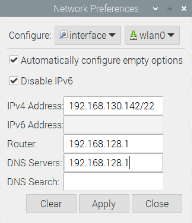
The infos on the static IP address are saved in a file in the /etc folder called /dhcpcd.conf. Normally the mask is /24 but we need /22 in our school network (4 bundles networks).
Command line
If you need to add a net mask (as we do) it is better to use the command line!
Call the midnight commander sudo mc and open the file dhcpcd.conf in the /etc folder. Press F4 to open the nano text editor and uncomment the following lines in /etc/dhcpcd.conf. Change the IP addresses to your needs (alternatively use sudo nano /etc/dhcpcd.conf).
    # Custom static IP address for eth0.
    interface eth0
    static ip_address=192.168.130.142/22 # normally 24 but 22 in our school network
    static routers=192.168.128.1
    static domain_name_servers=192.168.128.1

    # Custom static IP address for wlan0.
    interface wlan0
    static ip_address=192.168.130.142/22 # normally 24 but 22 in our school network
    static routers=192.168.128.1
    static domain_name_servers=192.168.128.1
Save the file with Ctrl-O, exit with Ctrl-X , exit mc with F10 and reboot (sudo reboot). Now we can log in with the new IP.
If we can mount the SD card on our PC, we can also add the infos to /etc/dhcpcd.conf before powering up the Raspi.
Use VNC Viewer
It is very convenient to work on the Raspberry Pi by remote control. A VNC (graphical desktop sharing system) server is already installed on the Raspi. It can be enabled by using the following command:
sudo raspi-config
Go to 5 Interfacing options and enable P3 VNC, P4 SPI, P5 I²C and P7 1-Wire. Reboot the Raspi.
You can also use the GUI (Preferences > Raspberry Pi Configuration > Interfaces to do so.)
On our computer or mobile device we need to download and run VNC Viewer from realvnc.com. VNC Viewer transmits the keyboard, mouse or touch events to the VNC Server on the Raspi, and receives updates to the screen in return.
Start VNC Viewer and type the IP address from the Raspi. In a window you are now able to control the Raspi as though you were working on itself. More infos on raspberrypi.org.
Further infos about the Raspberry Pi under http://weigu.lu/sb-computer/raspi_tips_tricks.
Learning Python
Let's write a little Python "Hello World" program for the Raspi. If you don't know Python, you will learn it in a blink.
Python is a powerful, high-level, object-oriented, open source programming language that's easy to use, because it has a very clean and readable syntax. Python is easy to learn and has a user-friendly data structures. Python also runs on all operating systems and is so powerful because of thousands of libraries (modules).
The Pi in Raspberry Pi stands for Python (the Raspberry is a reference to a fruit naming tradition in the old days of microcomputers).
Python is an interpreted language, meaning the interpreter executes instructions directly one by one. There exist two versions, Python 2.x and Python 3.x. Python 2.x should not be used any more for programs.
We use Python 3.x for our programs. The command on the Raspi is:
python3 filename.py
"Just do it" Buses 1:
- Open
Thonny, a Python3 development environment (menu (raspberry) > Programming). Type the following command in the Shell:print("Hello IoT"). Document the output.
Read the following page and test the examples: https://littlebirdelectronics.com.au/guides/189/introduction-to-python-with-raspberry-pi.
Read one of the following tutorials with basic python examples. Program the examples on your own and test them.
In English: http://staff.ltam.lu/feljc/software/python/python_basics.pdf.
In German: http://weigu.lu/tutorials/python_and_raspi/00_python_basics/index.html.
All the structuring in Python is done with indentation. In Arduino (C,C++) we use curly braces { and } to structure the code.
In Python we indent by 4 spaces. Don't use tabs!
Python code can be written with any editor. The file is saved in "text only" with the extension .py.
The first line of if statements (if...elif...else), for and while loops, functions and try...except statements end with a colon ":".
Using the GPIO's
Now to our first hardware "Hello World" program, the blinking LED.
"Just do it" Buses 2:
- Do the following wiring (calculate the resistor value).

Test the following program. Explain line by line what is done. Research the net if something is unclear.
   #!/usr/bin/env python3
   # -*- coding: utf-8 -*-
   # buses_gpio_blink.py

   import RPi.GPIO as GPIO  # sudo apt-get install rpi.gpio
   from time import sleep
   PIN_LED = 17
   GPIO.setmode(GPIO.BCM)   # Broadcom SOC channel number (numbers after GPIO)
   GPIO.setup(PIN_LED, GPIO.OUT)
   try:
       for i in range(0, 10):
           GPIO.output(PIN_LED, GPIO.HIGH)
           sleep(0.5)
           GPIO.output(PIN_LED, GPIO.LOW)
           sleep(0.5)
   except KeyboardInterrupt:
       print("Keyboard interrupt by user")
   GPIO.cleanup()
Let's add a switch or push-button (wire to
GNDor +3.3 V). Test the following program. Explain the new added lines.
Our circuit behaves magically like a circuit we tried in electronics fundamentals (ELEFU). We know that a pull-up or pull-down resistor is missing.
The Raspberry Pi has built-in pull-up and pull-down resistors which can be enabled in software with the following syntax:GPIO.setup(port_or_pin, GPIO.IN, pull_up_down=GPIO.PUD_UP)(alternativelypull_up_down=GPIO.PUD_DOWNfor a non inverting logic). Retest and document the program with an internal pull-down resistor.
To stop the program, typeCtrl+Cin the shell window.#!/usr/bin/env python3 # -*- coding: utf-8 -*- # buses_gpio_read.py import RPi.GPIO as GPIO # sudo apt-get install rpi.gpio from time import sleep PIN_LED = 17 PIN_SWITCH = 27 GPIO.setmode(GPIO.BCM) # Broadcom SOC channel number (numbers after GPIO) GPIO.setup(PIN_SWITCH, GPIO.IN) GPIO.setup(PIN_LED, GPIO.OUT) try: while (True): state_sw = GPIO.input(PIN_SWITCH) if state_sw == 0: GPIO.output(PIN_LED, GPIO.HIGH) else: GPIO.output(PIN_LED, GPIO.LOW) sleep(0.5) except KeyboardInterrupt: print("Keyboard interrupt by user") GPIO.cleanup()
Pycodestyle
If you want to code in an pythonic style, you can use pycodestyle to check formatting rules. The language's core philosophy is summarized in the document The Zen of Python. One of the principles is : Beautiful is better than ugly :)
pip3 install pycodestyle
To check your program use:
pycodestyle filename.py
1-Wire (wiki)
1-Wire is a device communications bus system designed by Dallas Semiconductor. It is possible to use only 1 wire (2 wires including ground) because power can be delivered over the data line when inactive. The voltage may range from 2.8 V to 6 V and the sensors have an internal capacitor to store the energy over a short time period.
The serial asynchronous half-duplex interface is similar to I²C but slower and it can cover bigger distances (up to 750 m). The bus takes one master and up to 100! slaves. Each slave has an unique 64-bit address (8-bit family-Code, 48-bit serial number, 8 bit CRC checksum), that is burned in the chip during production.
A popular IC using this bus is the DS18B20 temperature sensor. The temperature range is from -55 °C to +125 °C. The accuracy is high with less than ±0.5°C error between -10°C and +85°C). The internal ADC has 12 bit and the conversion needs about 750 ms.
The data wire has to be on high potential when inactive, because the master and the slaves pull the wire to ground when transmitting data. So we need a pull-up resistor. The current through this resistor should be about 1 mA, so 4.7 kΩ is a good value if we use 5 V, and 2.7 kΩ is a good value for 3.3 V. The driver of the Raspi is configured to use pin 4 for 1-Wire . We use here the 3 wire variant, because data communication is more robust with a supplementary 3.3 V power wire.

Take care not to cause short circuits when wiring. The Raspi's GPIO pins are not as robust as those of various microcontrollers! If the rpibuffboard adapter (http://www.weigu.lu/sb-computer/rpibufferboard) is used, set the jumper to 3.3 V.
The drivers for the Raspi's 1-Wire bus are not hard-coded into the kernel, but must be loaded via kernel modules at startup. If a Raspi image with graphical user interface is used, the 1-Wire interface can be enabled under Menu > Preferences > Raspberry Pi Configuration > Interfaces. For a Raspi without graphical interface this is done with the command sudo raspi-config (5 Interfacing options, P7 1-Wire). Both commands enable a line in the file boot/config.txt. With the command lsmod you can check which kernel modules are loaded. For 1-Wire the modules are called w1-therm, w1_gpio and wire).
In Linux everything is a file! This is also true for our 1-Wire sensor.
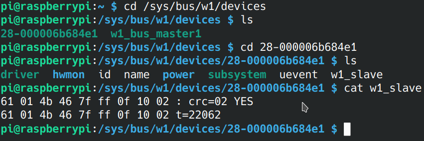
If the sensor is wired correctly, the driver takes care of requesting the unique address and creates a directory for the sensor with this address in the following subdirectory: /sys/bus/w1/devices. The name of the directory is the unique address (without 8 bit CRC checksum) of the sensor. 0x28 is the 8 bit family code. The hyphen is followed by the 48-bit serial number (6 bytes). As the sensor is treated like a file the device file has the name w1-slave and contains two text lines. The content of the file can be displayed with the cat command (or in midnight commander with F3).
Our Python program must only read the file and parse the temperature:
#!/usr/bin/env python3
# -*- coding: utf-8 -*-
# buses_w1_ds18b20_1.py

DEVICE_FILENAME = "/sys/bus/w1/devices/28-000006b684e1/w1_slave"

with open(DEVICE_FILENAME, 'r') as f:
    line1 = f.readline()
    print(line1, end='')
    line2 = f.readline()
    print(line2, end='')
To access the file we use the with statement because it automatically closes files after our operations and thus facilitates the code. After opening the file (r for read), we read the lines and use the print()-method with the supplementary argument end='' to suppress the newline character of the method.
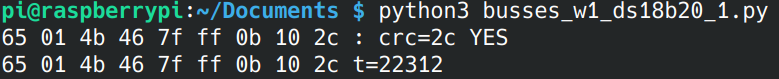
The required information is located in the 2nd line after the string
t=. With the find() method the temperature string can be extracted
and converted into a number. All the temperature readings are packed into a
function, that returns a number. A possible version of the program could look like the following:
#!/usr/bin/env python3
# -*- coding: utf-8 -*-
# buses_w1_ds18b20_2.py

from time import sleep

DEVICE_FILENAME = "/sys/bus/w1/devices/28-000006b684e1/w1_slave"


def read_temp():
    """ Read the temperature. """
    with open(DEVICE_FILENAME, 'r') as f:
        line1 = f.readline()
        line2 = f.readline()
    pos = line2.find("t=")
    if pos != -1:
        temp_string = line2[pos + 2:]
        temp = round(float(temp_string) / 1000.0, 1)
    else:
        print("error: temperature not found")
    return temp


try:
    while (True):
        print(str(read_temp())+" °C")
        sleep(1)
except KeyboardInterrupt:
    print("Keyboard interrupt by user")
The program can be stopped with CTRL+C.
"Just do it" Buses 3:
Test both programs from above.
It is annoying to search manually the address of our sensors. To automate this we will use theglobmodule of Python, which allows to search for pathnames using wildcards. Since the address of the DS18B20 always starts with the number28, the family code, we can use this to determine the directory. The methodglob()returns a list of devices. The string is located in the first element of the list to which we refer with the index [0]. Extend your program with the following lines and test it. Document the program and the output.from glob import glob try: device_folder = glob("/sys/bus/w1/devices/28*") except: print("Error: Sensor not found") device_file = device_folder[0] + "/w1_slave"
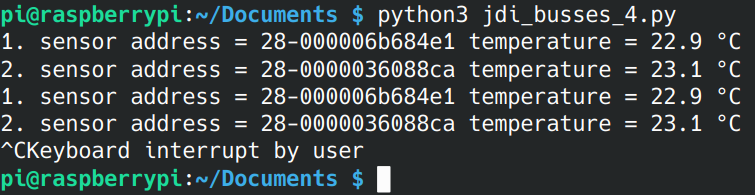
"Just do it" Buses 4:
- We want to measure temperatures with two temperature sensors. Change your program accordingly. The
read_temp()function will take thedevice_filevariable as a parameter. Withglob(), the second directory can be accessed with the index[1]. Document the program and the output. It should look like this:
I²C (wiki)
I²C (Inter-Integrated-Circuit) was developed by Philipps (now NXP) intended for communication between IC's in Audio and Video devices. It is a synchronous, half-duplex interface on a (multi)master/slave bus. Many special IC's can be used directly on this bus. The IC's have an own fixed or partly selectable address. More than one master can be used on the bus (multi-master), but normally the master (in our case the Raspi) transmits and a slave responds. I²C is a superset of the Intel's SMBus. On AVR controller the interface is called TWI (two-wire-interface).
Advantages of the I²C bus are the low wiring effort and the low costs in the development of a device. A microcontroller can control a whole network of IC's with only three wires and simple software. This lowers the costs of the device to be developed. During operation, chips can be added to or removed from the bus (hot-plugging).
Disadvantages of the I²C bus are the low speed and the small bridgeable distances. Data can only be sent alternately over the data line (half duplex), and in addition to the data, the addresses of the chips must be sent. It is not suitable for longer distances (low interference immunity).
Application:
The I²C bus is mostly used for the transmission of control and configuration data, where speed is not so important. It is used e.g. for real-time clocks, volume controls, sensors, A/D and D/A converters (ADC, DAC) with low sampling rates, EEPROM memory chips or bidirectional switches and multiplexers.
Four speeds can be used depending on the IC's:
- 100 kHz ( standard mode )
- 400 kHz ( fast mode ; erweiterter Adressraum )
- 1 MHz ( fast mode plus )
- 3,4 MHz ( high-speed mode ).
- 5 MHz ( ultra fast mode ).
The higher speeds (1 Mbit/s, 3.4 Mbit/s, 5 Mbit/s) are possible but reduce the length of the connecting wires.

In the picture one master and three slaves are shown. The synchronous I²C bus requires a Serial Clock Line (SCL), a Serial Data Line (SDA) and ground (GND). Each data bit on the SDA line is synchronized with the clock of the SCL line. The pull-up resistors on the clock and data lines pull both lines to high level in idle state. As for 1-Wire all devices connected to the bus have an open collector (bipolar transistor) or open drain (FET) output (the collector or drain of a transistor is open (not connected) and gets connected to power (VCC) by the common pull-up resistor of the bus). If the bipolar transistor or FET is activated, the bus is pulled to ground. Such a circuit is called a wired AND connection, because the circuit acts like an AND gate.
The I²C protocol and addressing
With a falling edge on SDA (SCL = High) the master starts the communication. After the start bit, the master first sends the address byte to the slave. The address byte consists of a 7-bit slave address and a read-write bit, which determines the direction of communication. The slave confirms the correct reception with an ACK confirmation bit (ACKnowledgement). The master generates the 9 clock pulses and then reads the clock line. Here a slow slave with a low level can then force a waiting time (clock stretching).

Depending on the direction of the communication, the master or slave now sends any number of data bytes (8 bits, MSB first). Each data byte is confirmed by an ACK bit (low level). The transmission is aborted by the master or slave sending a NACK bit (Not ACKnowledge, HIGH). With a rising edge on SDA (SCL = HIGH) the master releases the bus again (stop bit).

To save time the master can continue without releasing the bus (no stop bit) and start a new communication with another start bit (Repeated Start). The communication direction can of course be changed at will. The address byte sent by the master consists, as described, of seven bits that represent the actual address of the slave and an eighth bit that determines the read or write direction. The I²C interface uses an address space of 7 bits, which means that 112 devices can be addressed simultaneously on one bus (16 of the 128 possible addresses are reserved for special purposes). Each I²C-capable component (IC) has a fixed address. Some IC's, have the possibility to change a part of the address with control pins. This allows e.g. to use up to eight similar IC's on one I²C bus. More and more often the address can also be reprogrammed by software (e.g. for digital sensors). There is also a newer alternative 10 bit addressing (1136 blocks). It is downward compatible with the 7-bit standard (uses 4 of the 16 reserved addresses additionally).
I²C with the Raspberry Pi
As for 1-Wire, the I²C interface can be switched on with raspi-config in terminal or via the menu if a Raspi image with a graphical user interface is used (menu > Preferences > Raspberry Pi Configuration).
The new Raspbian automatically takes care of several steps here. To use the I²C bus the appropriate kernel modules are loaded. With the command lsmod you can check which kernel modules are loaded. For I²C the modules are called i2c-dev and i2c-bcm2708. The packages i2c-tools and python3-smbus are already installed (if they are not installed, they can be installed with sudo apt install i2c-tools python3-smbus). To avoid having to run the programs with root privileges, the user pi now belongs to the group i2c. This can be verified with the command groups pi (if it is not the case you can use the command sudo adduser pi i2c).
The Real Time Clock (RTC) DS3231
The Raspi has no RTC. So if we start a Raspberry Pi the Raspi date and time is the 01/01/70 00:00:00. If a network is available the Raspberry Pi gets the time and date from the Internet using the Network Time Protocol (NTP). If the network is down, we have no accurate time for our IoT device (the Raspi :)). So lets use an RTC breakout board to test sending and receiving data on the I²C bus.
A real time clock continues to run even without external power supply because it uses a battery (usually a lithium button cell with 3 V). Maxim's DS1307 I²C device was often used as the real-time clock. Today it is mostly replaced with the DS3231, an RTC that is more accurate, faster (400 kHz), doesn't request an external clock crystal of 32.768 kHz, has 2 alarms and even a measures the temperature.
We will use an RTC breakout board populated with this chip.

"Just do it" Buses 5:
As seen we need two pull-up resistors on our bus. As for
1-Wiretheir should be at least 1 mA flowing through the resistor. The Raspi has already two hardware pull-ups. Look at the circuit of the Raspi (Pi 3 Model B+). What values are used? Locate the two resistors on the Raspi and document this with a photo and an extract of the circuit.Lets have a closer look to the breakout board (ZS-042). Research the circuit diagram of the breakout board. What other I²C chip beneath the
RTCis soldered to the board. What are the solder padsA0-A2for? What voltage is needed to power the board? The board contains supplementary pull-up resistors. Can we use the board like this or do we need to de-solder the resistances? Calculate the total pull-up resistance.What happens if we power the board with 5 V and use a 3 V Lithium battery (primary, not rechargeable, look at the diode in series with the resistor connected to the battery and VCC).
Why can't we power the board with 5 V when connecting the
I²Cbus to the Raspi? Connect the breakout board to your Raspi as shown in the image above.Document the address map of the
DS3231(data sheet) and read the chapters Address Map,I²CInterface and Clock and Calendar.
The Raspi has 2 I²C ports (i2c-0 and i2c-1). On the first Raspis port 0 was used. On newer Raspis port 1 (SDA1 (pin3) and SCL1 (pin 5)) is used. It is also possible to use port 0 but by default is is disabled.
After the RTC board has been connected we can use the i2c-tools to test if our bus works out. To do this, we enter the following command (1 stands for port 1):
i2cdetect -y 1
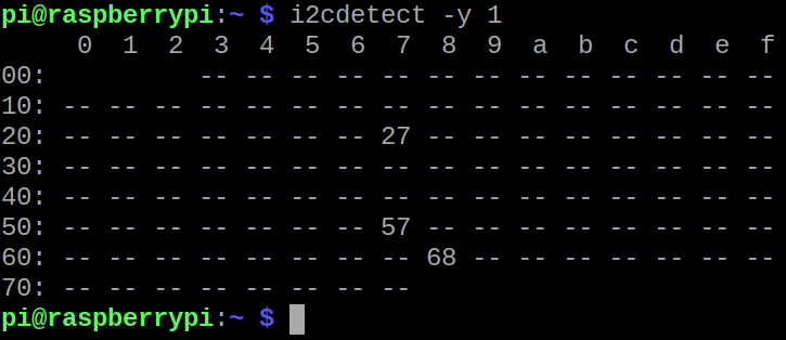
The output shows us all addresses of the connected I²C devices. In in our case the address 0x68 of the RTC .
"Just do it" Buses 6:
- Research what other devices are connected using the addresses
0x27and0x57and describe their purpose.
The clock module has 19 registers (RAM memory cells), which can be accessed via a register address. The first seven registers contain the data of the clock (time (3), weekday (1) and date (3)). As soon as the seconds register has been written (bit 7 (CH) = 0) the clock is running. The data is stored in BCD code (Binary Coded Decimal). BCD is a code with dual coded decimal digits. 4 bits (nibble) represent one decimal digit (0-9, 0b0000-0b1001).
Here a basic code in python to set the RTC:
#!/usr/bin/env python3
# -*- coding: utf-8 -*-
# buses_i2c_ds3231_1.py

from smbus import SMBus
from time import sleep

PORT = 1                # (0 for i2c-0, 1 for i2c-1)
Bus = SMBus(PORT)
RTC_ADDRESS = 0x68


def bcd_2_str(d):
    """ Convert BCD numbers to string.
        // for integer division; % for modulo. """
    if (d <= 9):
        return '0' + str(d)
    else:
        return str(d // 16) + str(d % 16)


def set_clock():
    """ Set the RTC clock.
        BCD: sec,min,hour,weekday,day,mon,year. """
    rtc_address_map = [0x00, 0x00, 0x08, 0, 0x01, 0x01, 0x20]
    Bus.write_i2c_block_data(RTC_ADDRESS, 0, rtc_address_map)


set_clock()
try:
    while (True):
        am = Bus.read_i2c_block_data(RTC_ADDRESS, 0, 7)
        time_str = (bcd_2_str(am[2]) + ':' + bcd_2_str(am[1]) + ':' +
                    bcd_2_str(am[0]))
        date_str = (bcd_2_str(am[4]) + '/' + bcd_2_str(am[5]) + '/' +
                    bcd_2_str(am[6]))
        print(date_str + ' ' + time_str)
        sleep(1)
except KeyboardInterrupt:
    print("Keyboard interrupt by user")
The class SMBus from the smbus library is used to access I²C. After creating the object Bus for port 1 we can access the bus with the methods write_i2c_block_data() and read_i2c_block_data() to send and receive a whole block of data to the bus. For our RTC we will send or read a memory block of 7 bytes, The BCD data is contained in a python list (called here rtcaddressmap).
The clock should of course be set only when the program is called up for the first time. This is done with the function set_clock(). After that the command should be deactivated with a comment character.
The write command inside the set_clock() function takes three parameters. The first parameter is the I²C address. The second parameter is a command from the master. In our case we can specify the start address of the RTC address pointer to the address map here (it is automatically incremented when the data is transferred). We pass zero as the starting address, so that the memory is written from the second address (with a one we would start at the minutes.) The third parameter is the list with the data to be written!
In the following infinite main loop the clock is read every second and date and time are output with print(). The reading of the RTC is done with the method read_i2c_block_data(). The first two parameters are the same as for the write method. The third parameter specifies the number of bytes to be read. Since the data is in BCD, it must be converted into a string. This is done by the function bcd_2_str(), using the integer division and the modulo operation.
"Just do it" Buses 7:
Test the program from above. To set the time we will now use the
NTPtime from the Raspi. For this we use thedatetimelibrary and a function to convert from decimal toBCD. Add the following code and set yourRTConce. Document the output.from datetime import datetime def int_2_bcd(d): # // for integer division; % for modulo return (((d // 10) << 4) + (d % 10)) def set_clock(): #set clock (BCD: sec,min,hour,weekday,day,mon,year) s = int_2_bcd(datetime.now().second) mi = int_2_bcd(datetime.now().minute) h = int_2_bcd(datetime.now().hour) d = int_2_bcd(datetime.now().day) mo = int_2_bcd(datetime.now().month) y = int_2_bcd(datetime.now().year-2000) wd = datetime.now().weekday() td = [s, mi, h, wd, d, mo, y] Bus.write_i2c_block_data(RTC_ADDRESS, 0, td)Extend the program so that the day of the week is added to the output. Document the program and the output. Use the following list:
WEEKDAY = ["Monday", "Tuesday", "Wednesday", "Thursday", "Friday", "Saturday", "Sunday"]Add the code to get the temperature with our
DS18B20, and add also the temperature to the output line. Document the program and the output.
"Just do it" Buses 8:
Next we will add an LCD display connected to an 8 bit port extender
PCF8574breakout board to theI²Cbus. Look at the data sheet of the port extender. The display needs 5 V, and the breakout board has two 4.7 kΩ pull-ups to 5 V. TheRTCboard works with 3.3 V and has also two 4.7 kΩ pull-ups. Calculate the voltage on ourSDAandSCLlines (1.8 kΩ and 4.7 kΩ on 3.3 V and 4.7 kΩ on 5 V). Is the voltage too high for our Raspi? If these is the case, what will be the solution?Use the informations on this page (click) to access the display. The library named
RPi_I2C_driver.pyis here (click). Enhance your program to show the date, time, temperature and the weekday on the display. To display the weekday we need to reduce the names to 3 characters. The degree sign on the display can be accessed with theß-sign. Document the program and the display output (photo).WEEKDAY_LCD = ["Mon", "Tue", "Wed", "Thu", "Fri", "Sat", "Sun"] time_temp_str_lcd = time_str + ' ' + temp_str + "ßC"
Adding MQTT
Next we add MQTT communication to our python scripts. First we need the paho MQTT python client from Eclipse. We install it with the following command:
sudo apt install python3-paho-mqtt
Here a basic example to use the library for publishing:
#!/usr/bin/env python3
# -*- coding: utf-8 -*-
# buses_mqtt_publish.py

import paho.mqtt.client as mqtt

MQTT_CLIENT_ID = "pi_iot_1"  # must be unique!!
MQTT_SERVER_IP = "192.168.128.82"
MQTT_SERVER_PORT = 1883
MQTT_TOPIC = "pi_iot_1/test"


def onConnect(client, userdata, flags, rc):
    """ Callback if CONNACK response from the server. """
    print("Connected with result code " + str(rc))
    mqttc.subscribe(topic, 0)  # Subscribe (topic name, QoS)


def onDisconnect(client, userdata, message):
    """ Callback that is executed when we disconnect from the broker. """
    print("Disconnected from the broker.")


def onSubscribe(client, userdata, mid, granted_qos):
    """ Callback that is executed when subscribing to a topic. """
    print('Subscribed on topic.')


def onUnsubscribe(client, userdata, mid, granted_qos):
    """ Callback that is executed when unsubscribing to a topic. """
    print('Unsubscribed on topic.')


def onMessage(client, userdata, message):
    """ Callback that is executed when a message is received. """
    print("message received ", str(message.payload.decode("utf-8")))
    print("message topic=", message.topic)
    print("message qos=", message.qos)
    print("message retain flag=", message.retain)


mqttc = mqtt.Client(client_id=MQTT_CLIENT_ID, clean_session=True)
mqttc.on_connect = onConnect   # define the callback functions
mqttc.on_disconnect = onDisconnect
mqttc.on_subscribe = onSubscribe
mqttc.on_unsubscribe = onUnsubscribe
mqttc.on_message = onMessage
mqttc.connect(MQTT_SERVER_IP, MQTT_SERVER_PORT, keepalive=60, bind_address="")
mqttc.loop_start()  # start loop to process callbacks! (new thread!)

try:
    while (True):
        mqtt_message = "{\"say it\": \"Hello:\"}"
        mqttc.publish(MQTT_TOPIC, mqtt_message)
        sleep(1)
except KeyboardInterrupt:
    print("Keyboard interrupt by user")
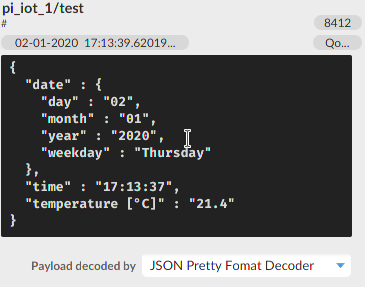
"Just do it" Buses 9:
- Add MQTT publishing to your last python script. The output in
MQTT.fxwithJSON Prett< Format Decoderenabled should look like in the following picture. Document your script (program) and the output ofMQTT.fx.
Interesting links
- https://www.raspberrypi.org/blog/raspberry-pi-imager-imaging-utility/
- https://learn.adafruit.com/i2c-addresses/the-list
- https://learn.adafruit.com/adafruit-ds3231-precision-rtc-breakout/
- https://circuitpython.readthedocs.io/projects/ds3231
- https://protosupplies.com/product/ds3231-rtc-with-eeprom-module/
- https://learn.sparkfun.com/tutorials/raspberry-pi-spi-and-i2c-tutorial/all
- https://cdn-learn.adafruit.com/downloads/pdf/adding-a-real-time-clock-to-raspberry-pi.pdf
- https://www.raspberrypi.org/documentation/hardware/raspberrypi/schematics/README.md
- http://www.circuitbasics.com/raspberry-pi-i2c-lcd-set-up-and-programming/
