Tutorials: Electronics fundamentals (ELEFU)
Hey Mr Ohm
last updated: 2022-09-22
Quick links
Beginning with this chapter we will come across many "Just do it" tasks. These tasks have to be carried out and have to be documented thoroughly!
Your marks will depend on the documentation!
Tip:
If you look for Electrotechnical (Electrical, Electronics) vocabulary in one of 20 languages, look here: https://electropedia.org.
Introduction
Without current no fun or as the German says "Ohne Strom nix los". If our batteries are empty the rover is virtually scrap. But what really powers the rover? What is electricity or energy and what is a current or a voltage? We will try step by step to refresh the basics.
Here a quote from Wikipedia/Electricity:
Electricity is the set of physical phenomena associated with the presence and motion of electric charge.
So let's begin with the electrical charge to warm up:
Electric charge (wiki)
In atoms we have electrons and protons, both hosting an electric charge. Neutrons have no charge. The electric charge is like mass a physical property of matter. It is difficult to explain what a charge or electricity really is. It is only possible to observe the effects and prove their existence by this effects.
The smallest unit of the charge called "elementary charge e" is very small, about 1.602·10−19 coulombs.
The symbol for the charge is often Q or q; the SI unit is the coulomb C or ampere-second As (ampere times second).
The charge of an electron is by convention negative −e and that of a proton positive +e.
Static electric charges create an electric field. Moving electric charges create an electric field and a magnetic field, called an electromagnetic field! If we bring a charge in an electromagnetic field an electromagnetic force is generated, which is one of the four fundamental forces in physics. Equal charges repel. Positive and negative charges attract each other.
Electric potential differences, called voltage, between points can be caused by electric charge. But what is a voltage respectively an electrical potential?
Voltage and potential (wiki)
Song of this subchapter: AC/DC > T.N.T > High Voltage.
Enough theory: Look at your batteries, remove them from the battery holder and read what's written on it. We have 4 alkaline AA or Mignon batteries with 1.5 V each.
V stands for Volt, and is the SI unit of the voltage. U is the symbol for voltage (in english publications often V).
The voltage is the cause and can exist on it's own.
When we switch the rover on, there will be a current, flowing through the circuit. The current arises only after pressing the switch and is the effect.
AC/DC
No Australian rock band ;).
A battery is a Direct Current DC power supply. The electric current generated by the battery only flows in one direction. The voltage does not change his direction.
The voltage and the current in Alternating Current AC circuits change direction periodically.
Measuring the voltages
On our batteries we noticed that the voltage should be 1.5 V.
Let's control if this is true. For this we use a voltmeter to measure the voltage between two points. Because we also want to measure other physical quantities we use a digital multimeter (DMM) which combines a multirange voltmeter, ammeter and ohmmeter.
To draw circuit diagrams, we need standardized symbols. We will use DIN EN 60617-2 (IEC 60617-2).
Symbol for a voltmeter in a circuit diagram:
The multimeter has a red and a black lead (cable). The leads have normally pointed probes and 4mm shrouded banana plugs (connector). To use the multimeter as voltmeter the red lead is connected to the banana jack with the V-sign and the black lead to the common socket mostly marked with COM. Turn the rotary switch to the position ⊽ or V-. We are measuring DC voltage!
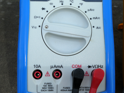
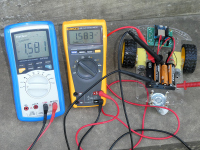
Voltage is the difference in electric potential between two points.
The two different potential of our battery are marked with plus (+) and minus (-). By convention we use the red lead for positive potential and the black (sometimes blue or brown) lead for the negative lead.
Symbol for a battery in a circuit diagram:
A voltmeter is always connected in parallel with a device to measure its voltage.
"Just do it" Ohm 1:
- Measure the 4 voltages of your 4 batteries and note the results.
- What happens if you interchange the leads?
A new battery has a voltage of about 1.6 V, an old battery a voltage of about 1.25 V.
Our AA alkaline battery is only one cell composed of an anode, a cathode and an electrolyte. In a battery the electrolyte can be liquid (often a type of acid) or solid (called wet cell or dry cell). The anode reacts with the electrolyte to produce electrons (-). The cathode reacts with the electrolyte and takes electrons (+).
"Just do it" Ohm 2:
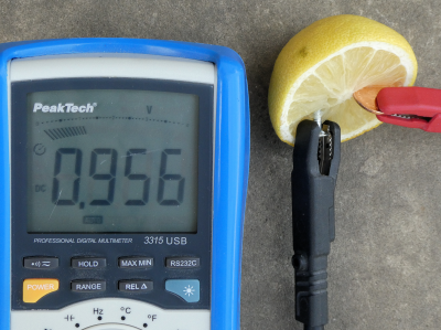
- We want to build our own lemon battery. You need a lemon (electrolyte, alternatives: apple or potato), a piece of zinc metal (galvanized nail) and a piece of copper (such as a piece of 5 eurocent). Measure the voltage of your own battery.
- What are the disadvantages of such a battery versus an alkaline battery?
Potential (wiki)
As stated above, voltage is the difference in electric potential between two points in a system. At our battery the two points are the anode and the cathode. The anode has an excess on electrons (-) and the cathode has a lack of electrons (+).
Even one single electron has an electric potential. For more information look at Coulomb's law.
For the potential we use the lowercase Greek letter phi φ.
To measure voltages we need a common reference potential. For our battery we define arbitrary that the negative pole (anode) has a potential of zero:
The Greek small letter PHI (φ) is used as symbol for the potential. The SI unit is Volt, the same as for the voltage.
The potential of the cathode is:
so we get for our voltage:
We use a blue arrow to visualise the voltage. The arrow is pointing from the positive charge to the negative charge if the voltage is positive.
The common reference potential is often named **GrouND (GND) or Earth. Earth is idealized as an infinite source or sink for charge, which can absorb an unlimited amount of current without changing. Earth is an arbitrary point to which potential of wiring things are rated. Even if our negative pole is now not connected with earth it is our reference.
GND) or Earth are a reference potential.It's similar to why we use sea level to measure height. The choice of our reference is deliberate! We could also use the earth's core instead sea level, so the mount Everest would be about 6379 km in height!!
To explain the potential, we can use the water analogy. The image shows two batteries with different potential. In our analogy these are different heights of our water level for the two tanks, witch gives the two water tanks different potential energy and thus different pressure. The pressure is directly proportional to the height (p = ρ·g·h; pressure = density of the liquid·gravity·height).
The pressure corresponds to the voltage in our water analogy.
It’s the pressure pushing the electrons (charge) through a material. The pressure acts on the closed water taps (infinite resistance), but there is no water flow.
Back to our batteries!
"Just do it" Ohm 3:
- Put all 4 batteries into your battery holder (switch off!). Now measure the voltages on all the different connection points.
- Disconnect the power header from your rover and turn the switch on. Measure the voltage on the connector (black and red wire).
- Draw by hand the circuit of your batteries with the right symbols and add the potentials and the voltage arrows.
The batteries are connected in series, to get a higher voltage. The motors need a minimum of 3V to rotate and 6V for full power.
As stated above, the choice of our reference is deliberate!
Normally our voltage arrows point to earth. If we change the direction of our voltage arrow from a negative potential to a positive potential, the voltage gets negative.
"Just do it" Ohm 4:
- How many possibilities are there to choose a reference point with 4 batteries?
- Add ground to your drawing. Comment your choice.
Current (wiki)
Song of this subchapter: Blue Man Group > The Complex > The Current.
Surly you want to open the two water tabs :). They act here like a switches (fully open or fully closed). Here is the result:
The water is flowing. Inside the battery the pressure (voltage) is maintained by chemical redox reactions. A water pump visualises these reactions. In the second battery these reactions are weaker because the battery is nearly empty. The water tabs are fully open. Because of less pressure the flow is weaker for the second battery.
Back to electricity:
The water flow corresponds to the current in our water analogy.
An electric current is a flow of electric charge.
Voltage is the cause. A current arises only when a voltage is present.
The voltage is the cause, the electric current is the effect.
As stated in the wiki: In electric circuits this charge is often carried by moving electrons in a wire. It can also be carried by ions in an electrolyte, or by both ions and electrons such as in an ionised gas (plasma)
.
Even if we talk about the flow of electrons, its is sufficient that the electron nudges its neighbour electron a little amount, who will nudge its next neighbour and so on until an electron reaches the device to power it. The long chain of momentum transfers between mobile charge carriers is explained by the Drude model.
Electric current causes heating (light bulbs) and creates magnetic fields (motors).
The symbol for the current is I, the SI unit is the base unit ampere A.
In our analogy a water tube stands for the wire. The wire is normally a metal and though a very good electrical conductor. The chemical bonds (for metals metallic bonding) explain the conductivity of metals. The electrons in a metal can easily change from one energy state into a slightly different one. They become delocalized and are forming a sea of free electrons that can be moved by an electric field.
If a wire is connected to the two terminals (poles) of a battery (DC voltage) we get an electric field across the conductor. The free electrons of the conductor are forced to drift toward the positive terminal under the influence of this field. So we get steady flow of charge (electrons) through a surface (cross section area) in the wire.
The current through a wire is the electric charge transferred through the surface (amount of electrons) over a period of time.
More generally:
A weird convention
In a wire the moving charged particles (charge carriers) are the negatively charged electrons. In e.g. semiconductors, the charge carriers can be positive or negative, depending on the dopant used. Positive and negative charge carriers may even be present at the same time, as happens in an electrolyte in our battery. A flow of positive charges gives the same electric current as an equal flow of negative charges in the opposite direction. A convention is needed for the direction of current that is independent of the type of charge carriers.
The direction of conventional current is arbitrarily defined as the same direction as positive charges flow.
Weird is the convention, because we often think in "electrons" as charge carriers. The electrons flow in the opposite direction of the conventional current flow in an electrical circuit!
We use a red arrow to visualise the current. The arrow points from + to - in a consumer load and from - to + in a generator (producer of energy like our battery).
Normally on a load the voltage arrow has the same direction as the current arrow!
If the current flows in the opposite direction, the current has a negative value.
When analysing a circuit, the direction of current through a circuit element is not always known. The current direction is assigned arbitrarily (often towards ground). When the circuit is solved, a negative value means that the actual direction of current through the circuit element is opposite that of the chosen reference direction.
Switching the current
We mounted and connected a simple on-off switch to our rover. It switches the positive wire of the battery holder, meaning it can interrupt the current to the motors and microcontroller. A closed switch has practically no resistance and the current can pass. An open switch interrupts the wire. The air gap between the poles gas a very high resistance and the passing current is nearly zero. A switch removes or restores the conducting path in a circuit when operated.
The used switch is a closer (SPST-NO: Single pole, single throw, normally open). The two terminals are normally disconnected (open) and are closed when the switch is activated.
Symbol for a switch in a circuit diagram:
Measuring the current
Electric current is measured with the ammeter (not amperemeter!).
An ammeter is always connected in series with the circuit, because the current has to flow through the ammeter.
In the water model you can compare the ammeter with the water meter.
Symbol for an ammeter in a circuit diagram:
To use the multimeter as ammeter the black lead stays in the common socket (COM). The red lead is connected to a banana jack with the A-sign.
There are two jacks for two different measuring ranges. The lower range is often 400mA (0.4A) and marked with 'mA'. Usually we don't know if the current will be under this threshold, so we start with the higher range (mostly 10A). The red lead is connected to the 10A jack.
The ammeter has integrated fuses. They prevent damage to the ammeter when the current is to high, so it is important to begin with the higher range and use the lower range only if the current is under 400mA. If the ammeter is not working, check the fuse and possibly replace it.
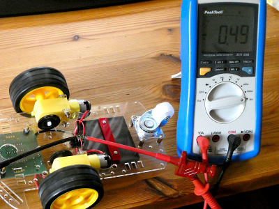
"Just do it" Ohm 5:
- Connect the red lead to
10Aand the black lead toCOM. Turn the rotary switch to the positionĀorA-. We are measuring a DC current!
The current has to flow through the ammeter, but how to open the circuit to insert the ammeter? By chance we have a switch. An open switch is an opening in our circuit. We connect the ammeter like shown in the following circuit diagram. Add a second multimeter as voltmeter! Measure the current and the voltage when no motor is running (microcontroller only). After this measure the currents and voltages with three different speeds (low, medium and fast).
- Create a calc (libreoffice) or excel sheet with 5 cases (rows): off, microcontroller only, slow speed, medium speed and fast speed. Fill in the measured values for voltage and current. Create three new columns with U·I, U/I and I/U. Calculate these values and fill them in. Search the internet for the names, symbols and units of the 3 physical quantities.
Resistance (wiki)
Song of this subchapter: Skillet > Victorious > The Resistance.
As seen above: The voltage is the cause and the current is the effect.
but there must be a third quantity that defines how much current will flow at a certain voltage. The missing link is the resistance R.
As stated in wikipedia:
The electrical resistance of an electrical conductor is a measure of the difficulty to pass an electric current through that conductor.
Electrical resistance shares some conceptual parallels with the notion of mechanical friction.
In the hydraulic analogy, current flowing through a wire (or resistor) is like water flowing through a pipe, and the voltage drop across the wire is like the pressure drop that pushes water through the pipe.
The resistance is proportional to how much pressure is required to achieve a given flow.
Water tabs could be used as variable resistance in the water analogy.
The symbol for the resistance is R, the SI derived unit is the ohm Ω.
Less used than the resistance is it's reciprocal the conductance G with the unit siemens S.
Conductor, insulator and semiconductor
Every material has a resistance. Copper Cu is often used as conductor because for the wire we want a very small resistance near zero. On the other hand we need sometimes a very high resistance so very little electric current will flow through it. Air is a good insulator. In our circuit we use the switch to change from insulator to conductor and vis versa.
Material with a resistance falling between that of a conductor and an insulator is called semiconductor. A famous semiconductor is Silicon Si. is essential to integrated circuits. All out 'IoT' world (Computer, phones ...) depends on it.
Resistance of a wire
Each wire has a resistance. Wire is also often used to build resistors (next chapter). To calculate the resistance of a wire we need the electrical resistivity or it's reciprocal the conductivity of the material.
The resistivity is a fundamental property of a material that quantifies how strongly a given material opposes the flow of electric current.
The symbol of the resistivity is the Greek letter ρ (rho). The SI unit is ohm-meter (Ω⋅m). The symbol of the conductivity is the Greek letter σ (sigma), but κ (kappa) (especially in electrical engineering) or γ (gamma) are also used. It's SI unit is siemens per meter (S/m).
Special alloys have high resistivity, so a shorter wire can be used. To get high stability of the resistor, the alloy's temperature coefficient of resistivity and corrosion resistance are important. Look here!
The longer a wire, the higher it's resistance. Resistance R is directly proportional to the length ℓ.
The thicker a wire (bigger cross section), the lesser it's resistance. Resistance R is inversely proportional to the cross-sectional area of the wire A.
The formula to calculate the resistance is:
"Just do (calculate) it" Ohm 6:
- We have a 50 meter cable extension to use our electrical power saw in the garden. The material of the cable extension is copper and it's cross-sectional area is 1,5 mm². Calculate it's resistance (the current is flowing back and forth!).
- We need a shunt (resistor) to measure a current of 10 A and want to build it on our own. The resistance should be 50 mΩ and we will use Constantan wire with a diameter of 2 mm. Calculate the needed length.
Resistor R (wiki)
Song of this subchapter: Yello > Pocket Universe > Resistor.
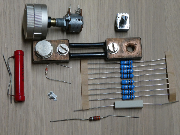
In electronic circuits we often need a component that implements electrical resistance. Fixed resistors have resistances that are constant and ideally don't change with temperature, time or operating voltage. They are used per example to reduce the current flow, to divide voltages or to terminate transmission lines. R (symbol of the resistance) is often used as name for a resistor.
Variable resistors are used to adjust circuit elements (e.g. volume control) or as sensing devices (e.g. NTC heat sensor). They have three terminals. 2 terminals (mostly both outer terminals) have a fixed resistance. The third terminal (mostly in the middle) is called the wiper.
Symbols for a resistor and a potentiometer (variable resistor) in a circuit diagram:
If the current through a resistor is too high, it will heat up. So beside the value R of the resistance in Ω the power P in Watt W is an important factor to consider.
Often an electronic color code is used to indicate the values resistors: https://en.wikipedia.org/wiki/Electronic_color_code. Also for there exist prefferred values that are used to produce Resistors:https://en.wikipedia.org/wiki/E_series_of_preferred_numbers.
"Just do it" Ohm 7:
- Read the two Wikipedia articles on colour code and preferred values. Take five different resistors and try to determine their value with the colour code. In which E-Serie are they located?
- Read the next chapter about measuring with the ohmmeter. Measure your five resistor values and compare the results with the determined values (calc or excel sheet).
Measuring the resistance
Electric resistance is measured with the ohmmeter.
Today's Ohmmeters have an electronic circuit that passes a constant current (I) through the resistance to measure the voltage (V) across the resistance.
An ohmmeter is always used on components that are not connected to a source!
Symbol for an ohmmeter in a circuit diagram:
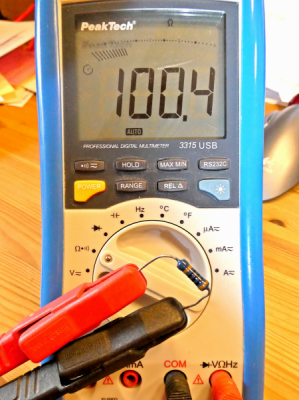
To use the multimeter as ohmmeter the black lead stays in the common socket (COM). The red lead is connected to a banana jack with the Ω-sign.
After choosing the right ohm-range, the leads are connected with both sides of the component, that we want to measure.
OHM's law (wiki)
Song of this subchapter: Kraftwerk > Radio-Aktivität > Ohm Sweet Ohm.

Thanks for the permission to Laura: https://www.hiphamshirts.com/
When R (and G) are constant, voltage and current are directly proportional to each other. This proportionality is called Ohm's law.
Or more generally (e.g. for AC quantities):
Voltage is like water pressure pushing the electrons (i.e. charge) through a material with a certain resistance.
Current–voltage characteristic (wiki)
The current–voltage characteristic (I–U curve) of a component is typically represented as a chart or graph and helps to get a very quick overview of the characteristic of a component. The electric current as the depending value (effect) is on the y-axes (vertical) and the voltage (cause) on the x-axes.
As a resistor is linear circuit element (constant) we get a straight line through the origin. If we compare to the mathematical equation of a straight line (see linear equation):
and we see that b = 0. If we compare with Ohm's Law:
we can deduce that the slope of the line equates to the inverse of the resistor 1/R.
source: https://www.grund-wissen.de
"Just do it" Ohm 8:
- Take two multimeter and a variable voltage source. Connect the voltmeter to the voltage source and measure the current through a resistor of 10 kΩ at different voltages (1 V to 10 V in steps of 1 V).
- Draw the circuit diagram by hand!. Don't forget to add the voltage arrows (blue) and the current arrow (red). The symbol for a variable voltage source looks like this:
- Use libreoffice calc or excel to document the measurement and to draw the graph
I=f(U).
"Just do it (with Arduino :))" Ohm 9:
- A potentiometer is a variable resistor and also a voltage divider. Read the wiki pages!
We take a linear potentiometer of 10 kΩ and connect the two outer terminals to 5 V and ground (GND).
Draw the circuit by hand and calculate the current. The current through the 10 kΩ resistor will be constant, so we get a proportionality between the voltage and the resistance on the wiperU~R! The wiper is the middle terminal. Test this with the voltmeter!
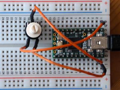
The wiper will now be connected to the analog digital converter (ADC) pin
A0(ADC0) of our Arduino (we use a Teensy 2.0, so the port pin isPF0(remove the voltmeter). The Teensy can also be used as power source.
As this analog pin draws only a very small current (1 µA), we can neglect the current (the load of the voltage divider is infinitely high, so we state that there is no load).
We measure the voltage on the wiper with theanalogRead()method and calculate the resistance (Ohm's law). The 10 bit ADC gives us a digital value from 0-1023 (210), with steps of 5 V/1024 = 4,88 mV.
To minimise the rounding error we calculate the resistance directly from the analog value. Test the following Arduino sketch. To see the results, activate the serial monitor! Document the monitor screen.
Try to understand the sketch and document it (what is int, float, long, ul, ...).// iot_jdi_O9_read_pot.ino // weigu.lu // 10k potentiometer 1->GND 2(PIN_WIPER)->A0 3->5V const byte PIN_WIPER = A0; // A0 (Teensy 2.0 PF0) unsigned int adc_value; float voltage; unsigned long resistance; void setup() { Serial.begin(115200); // Tools->Serial Monitor; set to 115200 bit/s } void loop() { adc_value = analogRead(PIN_WIPER); // read the input on analog pin voltage = adc_value*5.0/1024; resistance = (adc_value*10000ul)/1024; Serial.print("ADC value: "); Serial.print(adc_value); Serial.print("\tVoltage: "); Serial.print(voltage); Serial.print(" V\tResistance: "); Serial.print(resistance); Serial.println(" Ohm"); delay(1000); }
"Just do it (with Arduino :))" Ohm 10:
We are lazy but that doesn't mean that we are stupid!?
Manually measuring all the values to draw a graph is cumbersome. We will use Arduino to do this work for us :).
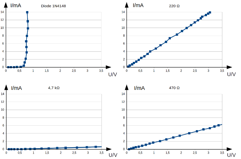
With Arduino we can use the Pulse-Width ModulationPWM(we will deepen this later) to easily create an analog voltage. The only additional component needed for this is a 4700 µF capacitor (Attention! polarized). We change the voltageUPWMin our sketch from 0 V to 5 V in steps of 0.2 V. The Byte variableOCR1Bis used for this. 28 = 255 is the maximum and corresponds to 5 V. Devices that are tested in a circuit (and thus are exchangeable) are called Device Under TestDUT. We will use 3 resistances (180 Ω, 560 Ω and 2.2 kΩ) and a diode (1N4148) to test. The diode is polarised! The terminal with the black line (cathode) has to be connected to the shunt. The current is measured as voltage on our 100 Ω shunt and calculated by Ohm's law.UDUT, needed for our diagram, is not measured directly but has to be calculated fromUPWMandUSHUNT. Build the following circuit on your breadboard.
Our circuit is not perfect. The range to measure is limited (Arduino can deliver only maximum 40 mA on a pin). This is also the reason for the high value of our shunt. We measure two voltagesUPWMon ADC1 andUSHUNTon ADC0. The total voltageUPWMshould equal the output voltage from the sketch (0 V - 5 V in steps of 0.2 V), but because our source is not ideal it's not. So we have to measure the real total voltage. Try to understand the core of the sketch.
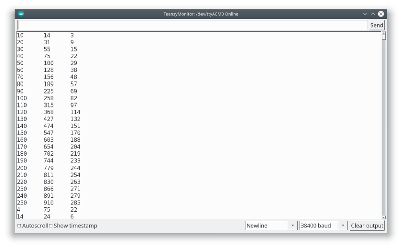
The sketch delivers for eachDUT25 values in the serial terminal. Copy these values to Libreoffice Calc or Excel and create the 4 diagrams as in the picture below. Document both the table and the diagrams.// iot_jdi_O10_make_diagram.ino // weigu.lu // PWM Out on PB6 (Teensy2); voltage out from 0-5V (step 0,2V) // measure total voltage and voltage on 100 Ohm resistor (current) const byte PIN_PWM_OUT = 15; // PB6 on Teensy 2.0 (OC1B of Timer1) const byte PIN_U_PWM = A1; // pin to read the total voltage const byte PIN_U_SHUNT = A0; // pin to read the current (voltage on shunt) byte i = 0; unsigned int current = 0, voltage = 0; void setup() { Serial.begin(115200); // Tools -> Serial Monitor pinMode(PIN_PWM_OUT, OUTPUT); // initialise fast PWM for Teensy Timer1 TCCR1A = 0xA9; // COM1A1, COM1B1, COM1C1, WGM10 TCCR1B = 0x0A; // WGM12 (Fast PWM 8 Bit) CK/8 -> 7,8kHz OCR1B = 0; // 0% } void loop() { i = i+10; Serial.print(i); Serial.print("\t"); // Tab OCR1B = i; // voltage out // read voltages on ADC0 (current) and ADC1 (Teensy 2.0 F0, F1) current = analogRead(PIN_U_SHUNT); // current voltage = analogRead(PIN_U_PWM); // total voltage // read 20 values and calculate average for better results for (int j=0;j<19;j++) { delay(2); current = current+analogRead(PIN_U_SHUNT); voltage = voltage+analogRead(PIN_U_PWM); } current = current/20; voltage = voltage/20; Serial.print(voltage); Serial.print("\t"); Serial.println(current); delay(500); }
"Just do (read) it" Ohm 11:
- To repeat and consolidate this chapter, read the article about the electricity basics (school of making Electronics 101) in the HackSpace Magazine (free pdf download) number 9 (page 76-81).
If you look for Electrotechnical vocabulary in one of 20 languages, look here: https://electropedia.org.
Interesting links
- Arduino for beginners in German: https://starthardware.org/
- Arduino for beginners in German: https://funduino.de/
- Get started with Arduino from HackSpace: https://hackspace.raspberrypi.org/books/arduino/pdf
- Cheat sheet in German (Grundlagen ET, Bruno Wamister): https://studylibde.com/doc/8271591/50ma-%3E50v---educa.unterricht
- Standardized symbols DIN EN 60617-2: http://student.4must.be/wp-content/uploads/2013/09/DIN-EN-60617.pdf
- The World's Online Electrotechnical Vocabulary: https://electropedia.org
• Links and Video links (contributed by David Mentz):
| Link | Quality (/5) | Language | Topic | |
|---|---|---|---|---|
| https://www.elektrotechnik-fachbuch.de/egrundlagenkap_01.html | 4,5 | DE | Grundlagen |
| Link | Quality (/5) | Language | Topic | Length (approx. in min) | |
|---|---|---|---|---|---|
| https://youtu.be/EcD7FlJ3Zsw | 5 | DE | Elektrotechnik - Grundlagen | 10 (first 10 min) | |
| https://www.youtube.com/watch?v=Qu3j6Wr-lYE | 5 | DE | Elektrotechnik - Grundlagen | 19 | |
| https://youtu.be/xI3jE4YRq2w?si=hYC68okh6kW_77Nm | 5 | DE | Stromkreis | 2 | |
| https://youtu.be/VKe9EDWiwf4?si=dmrKrb1OJVoB4rOK | 5 | DE | Stromkreis Wassermodell |
9 | |
| https://youtu.be/f6CZ0Rh1WE4?si=3vbovCNtsru1kSjj | 5 | DE | Spannung (1) | 5 | |
| https://youtu.be/pn1GyEbWj4g?si=_kyw7VQ3ablrBeJy | 5 | DE | AC/DC | 6 | |
| https://youtu.be/E05yKVzDCuY?si=UNI19WmdGbvFZNCx | 5 | DE | Strom | 6 | |
| https://youtu.be/1kINmhS3fA8?si=qBCDvZUrnb6FNJ74 | 5 | DE | Widerstand (1) | 4 | |
| https://youtu.be/DxSCvJhnJfM?si=0Ak0qiLkNIHqB0Uy | 5 | DE | Widerstand (2) | 7 | |
| https://youtu.be/Fdsce_MkIss?si=An2pvJpPC9PM55Jq | 5 | DE | Widerstand-kennlinien | 6 | |
| https://youtu.be/GkbuFchvcTk?si=8Y8MtaPITizHELW9 | 5 | DE | OHM (1) | 4 | |
| https://youtu.be/6QkYh1ndGNw?si=0C8tgR46YBwVjPBe | 5 | DE | OHM (2) | 9 |
