Tutorials: Electronics fundamentals (ELEFU)
The rover
last updated: 2021-09-12
Quick links
- Introduction
- Bill of materials (BOM)
- Mechanics
- PCB assembling and soldering
- Programming the ESP32 with Arduino
- Finish an first test
- Circuits
- Downloads
- Interesting links
Introduction
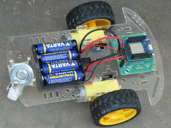
To work, we need hardware :), so each student builds his own rover. The rover is WLAN controlled by a computer or phone. We will use the rover or parts of it in our experiments and "just do it" exercises.
Bill of materials (BOM)
- 1 robot car chassis (kit)
- 1 microcontroller board: MH-ET LIVE D1 mini ESP32 with headers
- 1 PCB (see Downloads)
- 1 IC L293D (motor-driver)
- 1 IC socket 16-pins
- 1 diode 1N4004 or 1N4007
- 2 capacitors 100nF
- 2 8-pin headers female
- 3 2-pin headers male (included with the microcontroller board)
- 3 2-pin headers female
- 1 red bar 60x10 with 2 holes (washer for the battery holder)
- 2 screws M2x10 + nuts
- 2 screws M3x10 + nuts + 5mm spacer (to fix the PCB)
- heat shrink tube (6x1cm)
- 4 batteries AA alkaline 1,5V
Mechanics
Most parts have to be mounted in the right direction. It is frustrating to unmount parts that are not mounted the right way, so stay concentrated and look twice at the pictures.
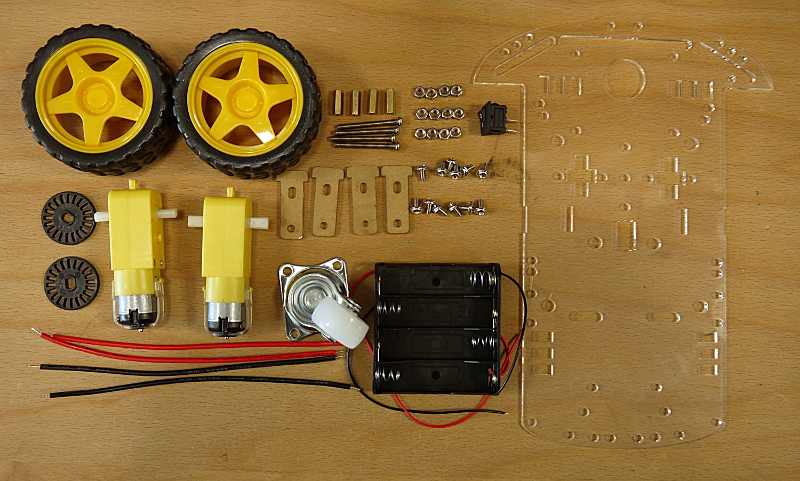
- Remove the protective film or paper from the acrylic glass plates.
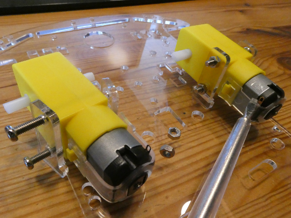
- Mount the 2 motors. You need 4 M3x30 screws an 4 M3 nuts.
Pay attention to turn the motor contacts to the insight (see screwdriver tip). The acrylic holders can break very easily so be gentle :).
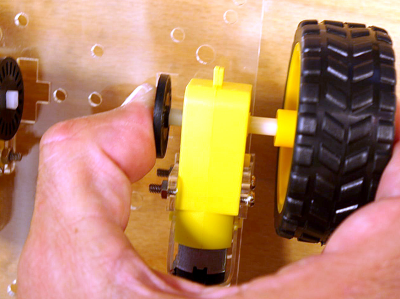
- Fix the wheels and encoder disks.
The acrylic holders can break very easily so be gentle :).
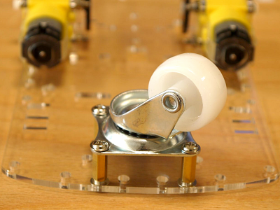
(Yes, i know that this is was already mentioned :)) - Mount the front wheel (4 spacer M3x12, 8 screws M3x6).
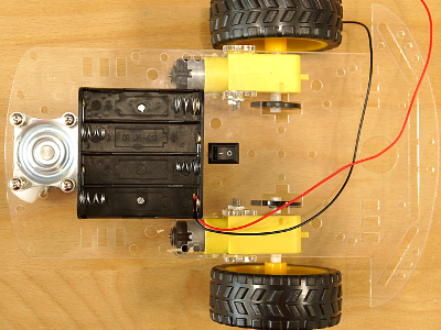
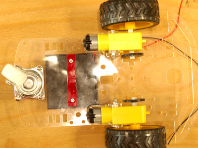
- Turn the chassis to mount the battery holder. It is fixed with 2 M2 screws. The red bar (60x10) with 2 holes is used as washer for the 2 nuts (mounted under the chassis).
- Push the switch in the square hole (click) near the battery holder.
PCB assembling and soldering
How to solder
There are many sites and videos on the net, so I will not reinvent the wheel. Here is a link, explaining soldering: https://www.sciencebuddies.org/science-fair-projects/references/how-to-solder Read the 6 Tabs carefully an then just do it :). Exercise is the best teacher.
Respect the following seven points:
- Clean always your tip of the soldering iron by wiping on a damp sponge or cleaning wool.
- Your PCB has to be free from dirt.
- Heat the connection (copper pad and lead from the component) with the tip of the iron for a few seconds before! applying the solder wire (a big pad e.g. GND plane needs more time to heat up!)
- Keep the iron tip on the connection as the solder is applied and use just enough solder to form good connection (see images on link above).
- Remove the tip from the connection as soon as the solder has flowed. Remove first the solder and then the iron. The whole process should take just a few seconds, so don't overheat the connection.
- Don't move the connection while the solder is cooling!
- Inspect the joint closely and if the connection looks bad, reheat it and try again.
Soldering
- Beginn by soldering the diode 1N4004 (or 1N4007). Pay attention, the diode has a polarity. The cathode (silver ring) is on the left (white ring on the PCB).
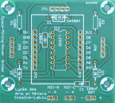
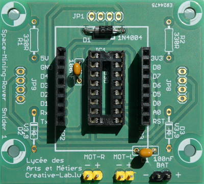
- Next is the IC socket. It has to be turned the right way. It has a little notch on one side. The notch can also be seen on the PCB (top under the diode). First solder 2 pins at the edges. We control that the socket sits flat on the surface. If not we correct this by reheating the pins. Afterwards we solder the remaining pins.
- Solder the 2 capacitors. They have no polarity.
- Separate three 2-pin male headers from the header bar and solder them.
- Now we solder the 4 headers to our microcontroller board. To get the two longer headers straight, it's a good idea to use a breadboard as helping hand. Always solder only one or 2 pins, control if the header sits straight and flat and solder only then the remaining pins.
- After this we solder the remaining 2 8-pin female headers to our PCB. For this we use the microcontroller board as help (second picture).
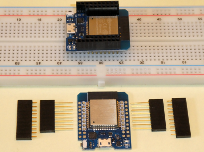
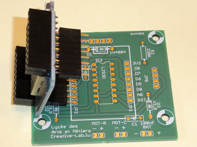
Connecting the motors
- Solder a red and a black wire to the motor contacts. The black wire is nearest to the acrylic plate!
- The wires pass the holes left and right from the switch.
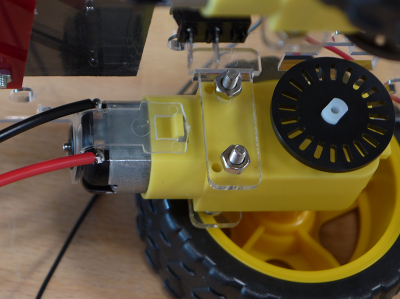
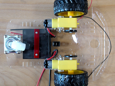
- Push a piece of heat shrink tube (1cm) over each wire. Then solder the wire to the female 2-pin header.
- Push the tubes over the soldering and heat the tube.
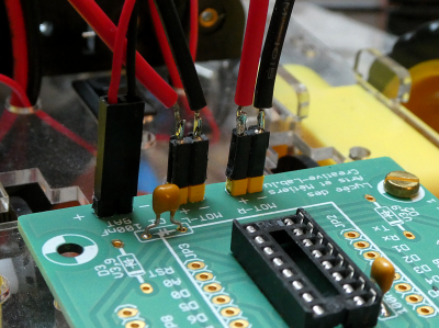
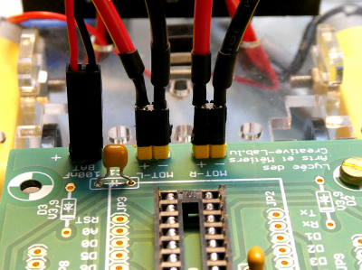
Connecting the battery holder and the switch
- Push the red wire of the battery holder (plus) through a hole in the acrylic plate. Shorten the wire and strip the isolation, so we can solder it to the switch. Take the second piece of the wire strip the isolation on two sides and solder it to the second pole of the switch. Push a piece of heat shrink tube (1cm) over the wire and get it back through the plate to the PCB. Then solder the wire to the 2-pin female header and heat the tube as seen with the motor wires.
- The black wire of the battery holder (minus) is soldered to the second pin of the header (don't forget the heat shrink tube).
Programming the ESP32 with Arduino
Installing Arduino
Download the latest Arduino software from Arduino.cc and extract the compressed folder. You can do this on a USB Stick. Now switch to the Arduino folder and create a folder with the name portable inside the Arduino folder.
A portable installation allows to carry around your personal set of sketches, cores and libraries, to be used on any computer without affecting it with your files (see here).
To be able to use Arduino with ESP32 we add the ESP32 framework simply by adding a text line to to "File > Preferences > Additional Boards Manager URLs:".
Enter the string
https://dl.espressif.com/dl/package_esp32_dev_index.json
into Additional Board Manager URLs: field. You can add multiple URLs, separating them with commas. So we also add the string:
http://arduino.esp8266.com/stable/package_esp8266com_index.json
to be able to use ESP8266 devices.
Now open Boards Manager from Tools > Board: > Boards Manager..., scroll down and install ESP32 and ESP8266 platform.
To use later Teensy Boards we download Teensyduino from the pjrc homepage and follow the instructions on this page to install it..
After the installation we select our ESP32 board MH ET LIVE ESP32MiniKit from Tools > Board) and choose the right port under Port.
Programming the ESP32
Download the following .zip-file and unzip it in your sketchbook folder:
In Arduino the C or C++ code files are named "sketch" have the extension .ino and must be contained in a folder with the same name (without .ino). In the same folder we have also the html page.
Download and uncompress the file rover_snyder1_both_esp_new_soft_with_websockets.zip to your portable/sketchbook folder. Open the file (File > Sketchbook > rover_snyder1_both_esp_new_soft_with_websockets).
The Arduino library Websockets from Markus Sattler has to be installed (Tools > Manage libraries... > search for websockets and scroll :)).
Change your SSID and Password in the sketch:
    const char *WIFI_SSID = "btsiot01";     // AP settings
    const char *WIFI_PASSWORD = "btsiot01"; // password must have min. 8 char.!!
Now we click on the Arduino Upload button  to compile and upload our sketch.
Finish an first test
- Control all soldering with a magnifying glass. Control all connections and make sure that there is no short circuit.
- The switch has to be on "Off" (0).
- Place the motor-driver IC (L293D) in the socket. The notch has to be on the same side than on the socket (direction of the diode).
- Fix the PCB with 2 M3 screws and 2 5mm spacers and connect the motors and the battery holder.
- Mount the microcontroller board. The USB connector faces the diode! (lock at the picture at the top of the page).
First Test
- Switch the rover on.
- The rover creates his own hot spot (you don't need another existing WiFi network) with his own SSID. Choose this network and log in with your password. First Test
- After your phone is showing
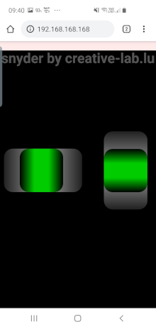
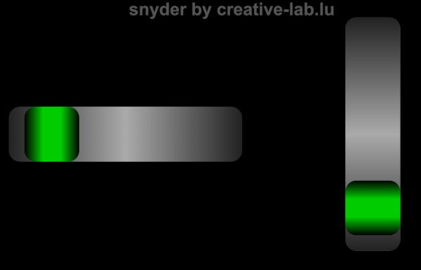
Connected, you start an Internet browser (best working with chrome!) and type the following URL:192.168.168.168/. Don't forget the slash ("/"). Now you see the two sliders to control your rover.

Circuits
The basic circuit is prepared to use two IR encoder and an I²C acceleration sensor.
Optional circuits
Here are two optional circuits.
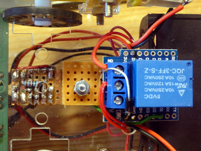
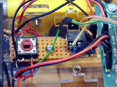
The first option is to add a relay and switch off the batteries after a certain amount of inactivity. For this we replace the original switch with a push-button.
The second optional circuit measures the battery voltage and current and sends the values over Serial or UDP.
They are possible because the ESP32 has more pins than an ESP8266. The relay is switched with GPIO33. Analog inputs are on GPIO34 and GPIO35.
You can activate the options in the software by uncommenting the corresponding line:
    #ifndef ESP8266
      //#define RELAY            // uncomment if you use a relay (only ESP32)
      //#define MEASURE          // uncomment if you use measure current (only ESP32)
    #endif // ifndef ESP8266
Downloads
Interesting links
- The rover using an ESP8266: http://weigu.lu/microcontroller/rover/index.html
• Video links (contributed by David Mentz):
| Link | Quality (/5) | Language | Topic | Length (approx. in min) | |
|---|---|---|---|---|---|
| https://youtu.be/GAyzaVSBvN0? | 3 | EN | Motor Driver 293d | 5 | |
| https://youtu.be/jAmDliHcTJ0? | 2 | EN | Motor Driver 293d | 22 | |
| https://youtu.be/Kb3Och2XC3A? | 2 | EN | Motor Driver 293d | 4 | |
| https://youtu.be/KKoduge9V50? | 2 | EN | Motor Driver 293d | 8 | |
| https://youtu.be/GPVC84D5ULw? | 4 | EN | DC Gear Motor | 10 | |
| https://youtu.be/AqvHogekDI4? | 4 | EN | Basic Soldering technique | 5 | |
| https://youtu.be/3a-bE1VlaU8? | 3 | EN | Assembly | 5 | |
| https://youtu.be/oQQpAACa3ac? | 4,5 | EN | Assembly and Encoders | 50 |
