Microcontroller projects
Watchdog tips and tricks
last updated: 2020-11-08
Feeding the watchdog
The watchdog timer (abbreviated WDT) reacts to a hardware or software malfunction by resetting the device after a certain time.
A watchdog timer is a counter that is regularly decremented. Properly functioning software will "feed" the watchdog in short intervals and reset the counter value. Faulty software will not do that and the watchdog counter will reach zero and resets the device.
ESP's have a hardware and a software watchdog. The time-out period of the software watchdog is about 3.2 s, that of the hardware watchdog about 8.2 s.
If the software watchdog bites we see a cause 2 in the serial terminal.
ets Jan 8 2013, rst cause:2, boot mode: (1,6)
If the hardware watchdog bites we see a cause 4 in the serial terminal.
ets Jan 8 2013, rst cause:4, boot mode: (3,6)
The loops must not take longer than 3 s, to avoid the watchdog to bite. But we can also reset the watchdog inside our software. This can be done with one of the following functions:
ESP.wdtFeed()delay()(not delayMicroseconds()!)yield()
They are integrated with the WiFi module so that a connection to a WiFi network is not lost as long as the software watchdog is fed. Unfortunately, I have noticed that things are not quite as smooth with regard to the MQTT library pubsubclient. So in those sketches that use that module, I call on local_yield() or local_delay() as defined in the link below if needs be.
An excellent article can be found on www.sigmdel.ca/michel. Interesting is also the part describing problems and giving solurions for the MQTT module pubsubclient.
Watch the watchdog: the watchdog reset counter
I had problems with two neopixel projects (neo clock and neo lamp). Both used the ESP8266 (Wemos D1 mini pro) and the Adafruit Neopixel library. In both projects I got watchdog resets, but only after 20-60 minutes; about 8 resets in 5 hours. To watch and count these resets and to be able to see if the problem remains after changing the code I programmed a little watchdog reset counter.
Hardware
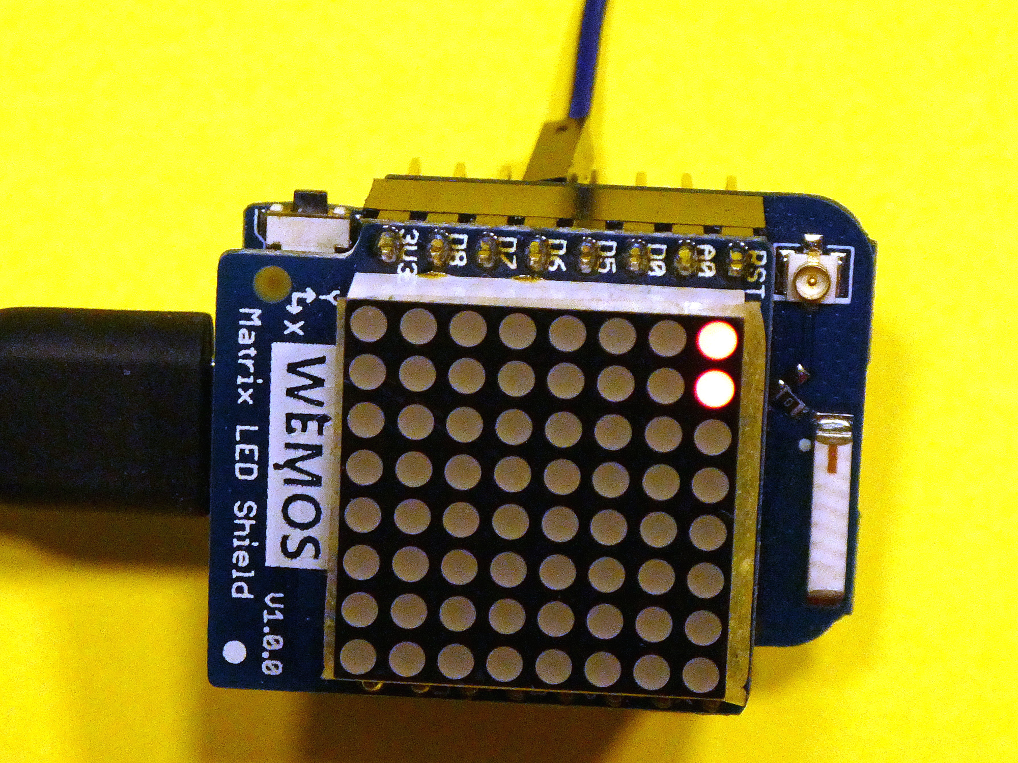
I had still an unused Wemos D1 mini LED matrix shield. As the resets are not frequent 8x8 LEDs let me count to 64, which is amply enough for this project.
We connect an arbitrary input pin (D5 (14) and D7 (13) are used by the matrix) called PIN_INPUT with an output pin (PIN_OUTPUT) of our microcontroller to be tested.
Software
We count rising edges on an input counter pin (PIN_INPUT) with the help of an Interrupt Service Routine (ISR).
In the setup of the program that we test we add the following lines:
    pinMode(PIN_OUTPUT,OUTPUT);
    digitalWrite(PIN_OUTPUT,LOW);
    digitalWrite(PIN_OUTPUT,HIGH);
    delay(100);
    digitalWrite(PIN_OUTPUT,LOW);
The output pin is an arbitrary free pin.
Here is the Arduino sketch for the watchdog reset counter:
    //  watchdog reset counter

    #include <Adafruit_GFX.h>
    #include <WEMOS_Matrix_GFX.h>

    MLED matrix(0); //set intensity=7 (maximum)
    const byte PIN_INPUT = 12; //D6
    volatile bool flag = false;
    byte count;

    void setup() {
      Serial.begin(115200);
      delay(500);
      Serial.println("\n8x8 Watchdog counter");
      pinMode(PIN_INPUT, INPUT);
      matrix.clear();      // clear display
      matrix.writeDisplay();  // write the changes we just made to the display
      attachInterrupt(digitalPinToInterrupt(PIN_INPUT), ISR, RISING);
    }

    ICACHE_RAM_ATTR void ISR() {
      flag = true;
    }

    void loop() {
      if (flag) {
        count++;
        flag = false;
        Serial.println(count);
        cnt2matrix(count);
      }
      delay(1000);
    }

    void cnt2matrix(byte count) {

      byte y = (count-1)/8;
      byte x = (count-1)%8;
      Serial.print(x);
      Serial.print("  ");
      Serial.println(y);
      matrix.drawPixel(x, y, LED_ON);
      matrix.writeDisplay();  // write the changes we just made to the display
    }
To get no watchdog resets with the watchdog counter we need to use the linker attribute ICACHE_RAM_ATTR for our Interrupt Service Routine. With this attribute we say that the function should be stored in the RAM. As the entire flash is used for the program and storage, reading and writing to the flash can be done only over 1 thread. Accessing the flash simultaneously over 2 different threads will probably crash the ESP.
