Microcontroller projects
ESP32 tips and tricks
last updated: 2024-02-29
Quick links
- MHEtLive ESP32-Mini-Kit (ESP-WROOM-32)
- ESP32 Pins (ESP-WROOM-32)
- Enable (EN) pin, maximum current per pin and hall effect sensor
- Configure Arduino
- Using Interrupt Service Routines
- Faulty boards (10/21) workaround
MHEtLive ESP32-Mini-Kit (ESP-WROOM-32)
The MH ET LIVE ESP32MiniKit has the form factor of the WEMOS/LOLIN D1 mini pro ESP8266 boards and is interesting if you want to replace such a board with an ESP32. Software Link: https://github.com/MHEtLive.
The blue LED can be accessed with LED_BUILTIN in Arduino. It is connected to GPIO2 (not related with the original WEMOS/LOLIN Pins) and uses positive logic since revision 1.1 (WEMOS/LOLIN D1 mini pro uses neg. logic!)!
!! Serial is not the same as for the Wemos D1 mini pro!! TxD and RxD are reversed. There is an error on the pinout! RxD is the outer pin. Arduino Serial2 is on GPIO17 (u2TxD) and GPIO16 (u2RxD).
Pin layout for MHEtLive ESP32-Mini-Kit and LOLIN/WEMOS D1 mini pro
Here is the pin layout of the MH ET LIVE ESP32-Mini-Kit and the pin compatible LOLIN/WEMOS Di mini pro:
| MHET | MHET | - | LOLIN | LOLIN | - | MHET | MHET | |
|---|---|---|---|---|---|---|---|---|
| GND | RST | - | RST | ------------ |
TxD | - | RxD(3) | GND |
| NC | SVP(36) | - | A0 | ------------ |
RxD | - | TxD(1) | 27 |
| SVN(39) | 26 | - | D0(16) | ------------ |
D1(5,SCL) | - | 22(SCL) | 25 |
| 35 | 18 | - | D5(14,SCK) | ------------ |
D2(4,SDA) | - | 21(SDA) | 32 |
| 33 | 19 | - | D6(12,MISO) | ------------ |
D3(0) | - | 17(TxD2) | TDI(12) |
| 34 | 23 | - | D7(13,MOSI) | ------------ |
D4(2,LED) | - | 16(RxD2) | 4 |
| TMS(14) | 5 | - | D8(15,SS) | ------------ |
GND | - | GND | 0 |
| NC | 3V3 | - | 3V3 | ------------ |
5V | - | 5V | 2 |
| SD2(9) | TCK(13) | ------------ |
TD0(15) | SD1(8) | ||||
| CMD(11) | SD3(10) | ------------ |
SD0(7) | CLK(6) |
And to use it in your code (copy paste):
      MH ET Live   |---|   Mini Kit              LOLIN/WEMOS |---| D1 Mini Pro

  GND    |  RST    |---|  3 RxD  |    GND        RST         |---|       TxD
   NC    |  SVP 36 |---|  1 TxD  | 27                 A0     |---|       RxD
  SVN 39 |      26 |---| 22 SCL  | 25                 D0 16  |---|  5 D1 SCL
      35 |  SCK 18 |---| 21 SDA  | 32             SCK D5 14  |---|  4 D2 SDA
      33 | MISO 19 |---| 17 TxD2 | 12 TDI        MISO D6 12  |---|  0 D3
      34 | MOSI 23 |---| 16 RxD2 |  4            MOSI D7 13  |---|  2 D4 LED
  TMS 14 |   SS  5 |---|    GND  |  0              SS D8 15  |---|       GND
   NC    |  3V3    |---|    5V   |  2            3V3         |---|        5V
  SD2  9 |  TCK 13 |---| 15 TD0  |  8 SD1
  CMD 11 |  SD3 10 |---|  7 SD0  |  6 CLK
ESP32 Pins (ESP-WROOM-32)
The ESP32 has the following peripherals:
- 18 ADC,
- 2 DAC,
- 3 UART,
- 2 I2C,
- 3 SPI,
- 16 PWM,
- 2 I2S
- 10 capacitive sensing GPIOs.
The ADC and DAC pins are static. The other pins can be changed in code because of the ESP32 chip’s multiplexing feature.
Build-in LED
The blue LED can be accessed with LED_BUILTIN in Arduino. It is connected to GPIO2 (not related with the original WEMOS/LOLIN Pins) and uses positive logic since revision 1.1! The old schematic in the net shows negative logic from the 1 version (V1.0). This is no more compatible with WEMOS/LOLIN D1 mini pro using neg. logic!
I/O pins
Even as pins can be defined in software, they are assigned by default. For example the MH ET Live ESP32 Mini Kit uses an ESP-WROOM-32. In the data sheet of the ESP-WROOM-32 we see that GPIOs 34, 35, 36 and 39 are input only pins (GPI) or that GPIO 6-11 are connected to the integrated SPI flash and can't be used as GPIO.
Don't use GPIO 6-11!
| Best pins for input and output: | |||||||||||||
|---|---|---|---|---|---|---|---|---|---|---|---|---|---|
| GPIO Nr | 13 | 16 | 17 | 18 | 19 | 21 | 22 | 23 | 25 | 26 | 27 | 32 | 33 |
| Pins for input only: | ||||
|---|---|---|---|---|
| GPIO Nr | 34 | 35 | 36 | 39 |
Some of the pins have a signal at boot or need to have a defined state at boot.
I/O pins to use with extra caution:
| GPIO Nr | IN | OUT | Remark |
|---|---|---|---|
| 0 | pulled up | OK | outputs PWM signal at boot |
| 1 | TX pin | OK | debug output at boot |
| 2 | OK | OK | connected to on-board LED |
| 3 | OK | RX pin | HIGH at boot |
| 5 | OK | OK | outputs PWM signal at boot |
| 12 | OK | OK | boot fail if pulled high |
| 14 | OK | OK | outputs PWM signal at boot |
| 15 | OK | OK | outputs PWM signal at boot |
The following strapping pins: 0, 2, 4, 5 (HIGH during boot), 12 (LOW during boot) and 15 (HIGH during boot) are used to put the ESP32 into bootloader or flashing mode. Don't connect peripherals to those pins! If you do, you may have trouble trying to upload code, flash or reset the board.
Hint from https://github.com/espressif/arduino-esp32: Sometimes to program ESP32 via serial you must keep GPIO0 LOW during the programming process.
Analog to Digital Converter pins (ADC)
The ESP32 has 18 x 12 bits ADC input channels.
ADC input channels (ESP-WROOM-32):
| ADC1 ch: | 0 | 1 | 2 | 3 | 4 | 5 | 6 | 7 | ADC2 ch: | 0 | 1 | 2 | 3 | 4 | 5 | 6 | 7 | 8 | 9 |
|---|---|---|---|---|---|---|---|---|---|---|---|---|---|---|---|---|---|---|---|
| GPIO Nr | 36 | 37 | 38 | 39 | 32 | 33 | 34 | 35 | 4 | 0 | 2 | 15 | 13 | 12 | 14 | 27 | 25 | 26 |
!! ADC2 channels cannot be used when Wi-Fi is used!!, so best use ADC1 channels.
The ADC's input channels have a 12 bit resolution (0 - 4095). The maximum voltage is 3.3 V. The resolution and the ADC range can be changed in code.
The ESP32 ADC in not very linear especially at the beginning and at the end. For more information look here.
Digital to Analog Converter pins (DAC)
| DAC's: | DAC1 | DAC2 |
|---|---|---|
| GPIO Nr | 25 | 26 |
UART pins
The three serial ports on the ESP32 (U0UXD, U1UXD and U2UXD) 3.3 V level. They are called UART0, UART1 and UART2.
UART0 is normally used by the serial monitor. UART2 (Serial2) is available on the GPIO pins 16 (RxD2) and 17 (TxD2). UART1 is connected to GPIO 9 and 10, but these are not available because they are connected to the integrated SPI flash. Fortunately ESP32 has multiplexing features, and so pins can be changed in code. This can be done with the begin command: Serial1.begin(9600,SERIAL_8N1, 21, 22);. With this command we define GPIO pin 21 for RxD1 and 22 for TxD1.
| UART0 (Serial) | Tx | Rx |
|---|---|---|
| GPIO Nr | 1 | 3 |
No CTS and RTS for UART0.
| UART2 (Serial2) | Tx | Rx | CTS | RTS |
|---|---|---|---|---|
| GPIO Nr | 17 | 16 | 8 | 7 |
I²C pins
On the ESP32 any pin can be set as SDA or SCL. There are 2 I²C channels. Arduino defaults are:
| I²C | SDA | SCL |
|---|---|---|
| GPIO Nr | 21 | 22 |
To use other pins in Arduino just call:
Wire.begin(SDA, SCL);
SPI pins
The default pin mapping for the two usable SPI channels are:
| VSPI | MOSI | MISO | CLK | CS |
|---|---|---|---|---|
| GPIO Nr | 23 | 19 | 18 | 5 |
| HSPI | MOSI | MISO | CLK | CS |
|---|---|---|---|---|
| GPIO Nr | 13 | 12 | 14 | 15 |
PWM pins
The ESP32 has an LED PWM controller with 16 independent channels.
All output pins can be used as PWM pins.
To set a PWM signal the PWM frequency, duty cycle, PWM channel, resolution and the used pin must be set in the code. AnalogWrite() is not available. Here a piece of code to use PWM:
    // esp32_test_pwm.ino  weigu.lu

    const int PWM_FREQ = 5000;             // freq limits depend on resolution
    const byte PWM_CHANNEL = 0;            // channels 0-15
    const byte PWM_RES = 8;                //resolution 1-16 bits
    const byte PWM_PIN = 16;

    void setup(){
      ledcAttachPin(PWM_PIN, PWM_CHANNEL); // assign pin to channel
      ledcSetup(PWM_CHANNEL, PWM_FREQ, PWM_RES);
    }

    void loop(){
      for(int duty_cycle = 0; duty_cycle <= 255; duty_cycle++){
        ledcWrite(PWM_CHANNEL, duty_cycle);
        delay(15);
      }
      for(int duty_cycle = 255; duty_cycle >= 0; duty_cycle--){
        ledcWrite(PWM_CHANNEL, duty_cycle);
        delay(15);
      }
    }
Or look at the Arduino LEDCSoftwareFade example (File > Examples > ESP32 > AnalogOut > LEDCSoftwareFade)
Capacitive touch pins
There are 10 internal capacitive touch sensors. The capacitive touch pins can among other things be used to wake up the ESP32 from deep sleep.
Those internal touch sensors are connected to these GPIOs:
| Touch sensor: | 0 | 1 | 2 | 3 | 4 | 5 | 6 | 7 | 8 | 9 |
|---|---|---|---|---|---|---|---|---|---|---|
| GPIO Nr | 4 | 0 | 2 | 15 | 13 | 12 | 14 | 27 | 33 | 32 |
Real Time Clock (RTC) pins
The following RTC pins can be used as external wake up source to wake up the ESP32 from deep sleep when the Ultra Low Power (ULP) co-processor is running.
| RTC | 0 | 3 | 4 | 5 | 6 | 7 | 8 | 9 | 10 | 11 | 12 | 13 | 14 | 15 | 16 | 17 |
|---|---|---|---|---|---|---|---|---|---|---|---|---|---|---|---|---|
| GPIO Nr | 36 | 39 | 34 | 35 | 25 | 26 | 33 | 32 | 04 | 0 | 2 | 15 | 13 | 12 | 14 | 27 |
Look here for more information.
Interrupt pins
All GPIOs can be configured as interrupts.
Enable (EN) pin, maximum current per pin and hall effect sensor
If you tie the enable (EN) pin ground the effect is a RESET (the pin is pulled up and to enable the 3.3V regulator.
The maximum current drawn per GPIO is 40 mA.
The ESP32 has a built-in hall effect sensor to detect magnetic fields!
Configure Arduino
Finally its possible to add the ESP32 framework simply by adding a text line to to "File > Preferences > Additional Boards Manager URLs:".
Copy the following line:
https://dl.espressif.com/dl/package_esp32_dev_index.json
to "File > Preferences > Additional Boards Manager URLs:".
Go to "Tools > Board:".." > Boards Manager..." and scroll down. Then click install.
Using Interrupt Service Routines
We need to use the linker attribute ICACHE_RAM_ATTR for our Interrupt Service Routines. With this attribute we say that the function should be stored in RAM instead in Flash. As the entire flash is used for the program and storage, reading and writing to the flash can be done only over 1 thread. Accessing the flash simultaneously over 2 different threads will crash the ESP and trigger a watchdog reset.
    ICACHE_RAM_ATTR void ISR() {
      flag = true;
    }
Faulty boards (10/21) workaround
Newer ESP32-Mini_Kit boards from China have a CH9102F IC instead of the old CP2104 for USB to serial bridge. You have to add the following line to your udev file in linux:
    # Wemos D1 mini pro with CH9102
    SUBSYSTEMS=="usb", ATTRS{idVendor}=="1a86", ATTRS{idProduct}=="55d4", GROUP="plugdev", MODE="0666"
Now we get a serial port (but ttyACM instead of ttyUSB!).
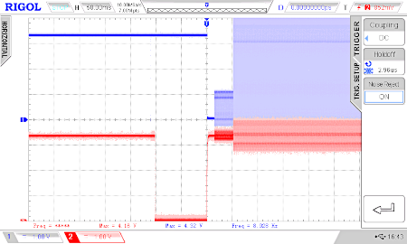
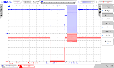
But the chip can not be programmed in Arduino because GPIO0 is not properly pulled down by RTS (more infos: http://weigu.lu/microcontroller/esp_programmer/index.html) as the following oscilloscope screen shows (right image, blue signal):


In the left image we see the signal as it should be. A workaround is to connect GPIO0 (IO0) shortly to GND while programming with Arduino (thanks Daniel :)).
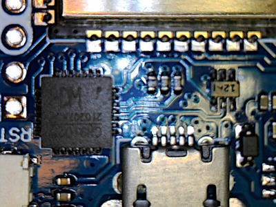
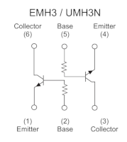
I found the culprit. If I'm not mistaken, they soldered a dual transistor SOT363 from LRC (MUN531DW1T1, marking 12) with a 22 k resistor between emitter and base (measured) and a 22 k resistor to the base. The original UMH3N from Rohm (right picture, marking H3) have only a 4.7 k to the base. These transistors are needed to tie down GPIO0 to GND.
I de-soldered an UMH3N from a bricked Wemos and exchanged the chips. This solved the problem!


Workaround
Connect GPIO0 (IO0) shortly to GND, just after the programming in Arduino starts.
As this is tedious if you have to program your chip multiple times, here a little helper program. Connect pin 33 of a a working ESP32 to GPIO0 (D3, IO0) of your ESP32 or ESP8266 with the false dual transistor chip, and interconnect the two grounds. Start the helper program and after this the programming of the problematic chip. The program detects the begin of the programming and pulls GPIO0 to GND at the needed moment for the needed time.
    /* workaround_no_UHM3N.ino
    * weigu.lu
    * connect ESP32 pin 33 or Uno pin A0 to GPIO0 (D3 or IO0) and
    * GND ESP32 (Uno) to GND ESP32 or ESP8266 with false chip
    */

    const byte PIN = A0;                //Arduino Uno A0, ESP32 GPIO 33
    const unsigned int THRESHOLD = 500; // 500 for Uno 3500 for ESP32
    unsigned int GPIO0_VALUE;

    void setup() {
      Serial.begin(115200);
    }

    void loop() {
      GPIO0_VALUE = analogRead(PIN);
      while (GPIO0_VALUE > THRESHOLD) {
        GPIO0_VALUE = analogRead(PIN);
        Serial.println(GPIO0_VALUE);
      }
      delay(20);
      GPIO0_VALUE = analogRead(PIN);
      while (GPIO0_VALUE > THRESHOLD) {
        GPIO0_VALUE = analogRead(PIN);
        Serial.println(GPIO0_VALUE);
      }
      Serial.println("Tie it to GND");
      pinMode(PIN,OUTPUT);
      delayMicroseconds(20);
      digitalWrite(PIN,LOW);
      delay(20);
      pinMode(PIN,INPUT);
      delay(10000);
      Serial.println("Do it again");
    }
